Drum brake device for small aircraft and working method

A braking device and aircraft technology, applied in drum brakes, brake types, aircraft braking arrangements, etc., can solve the problems of slow braking system response, increased diameter, increased brake pedal stroke, etc., to improve braking efficiency , Improve the braking response, the effect of the overall compact structure

Inactive Publication Date: 2020-04-10
NANJING UNIV OF AERONAUTICS & ASTRONAUTICS
View PDF12 Cites 2 Cited by
  • Summary
  • Abstract
  • Description
  • Claims
  • Application Information

AI Technical Summary

Problems solved by technology

However, in traditional drum brakes, the diameter of the drum of the drum brake will increase after being heated, causing the stroke of the brake pedal to increase, the pedaling force during braking is difficult to control, and the response of the braking system will slow down. , it is prone to the situation that the braking response is not as good as expected, which is not conducive to high-frequency braking action
At present, all drum brake devices are provided with hydraulic devices to provide power to the brake wheel cylinders so that the brake shoes open the friction plates and brake drums to generate braking force to achieve braking, but the power provided by the hydraulic devices to the brake wheel cylinders When the device is in use, it has the characteristics of slow response and inertia, which affects the emergency braking effect. At the same time, if the sealing effect of the sealing ring is not good, it will affect the braking effect

Method used


Image

  • Drum brake device for small aircraft and working method
  • Drum brake device for small aircraft and working method
  • Drum brake device for small aircraft and working method

Examples


Embodiment 1

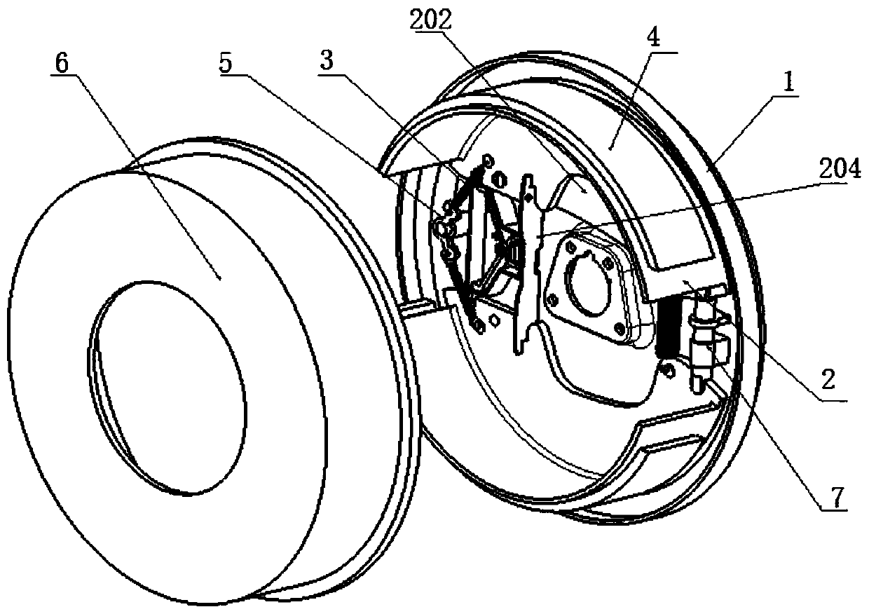
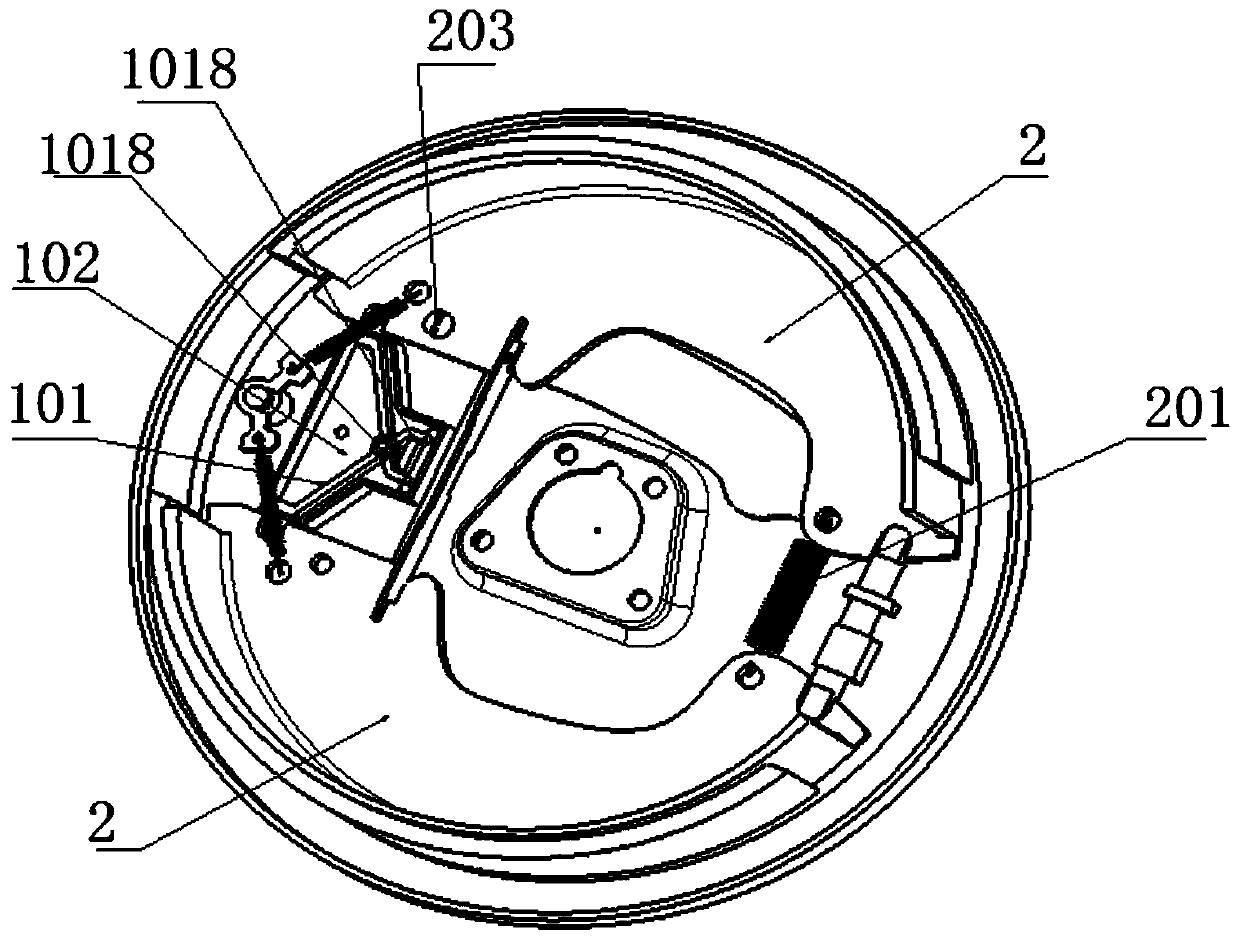
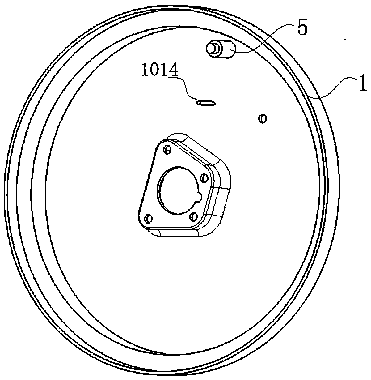
[0027] Embodiment 1: as Figure 1-5 As shown, a drum brake device for small aircraft described in this embodiment includes a base 1, two brake shoes 2 mounted on the base 1 through floating supports, and one end of the brake shoe 2 is provided with Back-moving spring 3, the outer surface of each brake shoe 2 is pasted with friction plate 4. A rotating bracket 5 is arranged between the two brake shoes 2 . The rotating bracket 5 is fixed on the base 1, and the two sides of the rotating bracket 5 are brake shoes 2, respectively provided with a return spring 3, one end of the returning spring 3 is fixed on the rotating bracket 5, and the other end is connected with a brake shoe 2 , when the brake shoe is displaced under the drive of the drive mechanism, the return spring 3 is used to pull the two brake shoes back to their original positions. A brake drum 6 is sheathed on the periphery of the friction plate 4 , and an adjustable push rod 7 connecting the two brake shoes 2 is prov...


PUM


Abstract

The invention discloses a drum brake device for a small aircraft and a working method. The brake device comprises a base and two brake shoes installed on the base through a floating support. A drivingmechanism used for driving the two brake shoes to be away from each other is installed between the two brake shoes, the driving mechanism comprises an amplifying mechanism, and the amplifying mechanism comprises a displacement input end, a displacement output end used for driving the two brake shoes and a piezoelectric stacking assembly used for driving the displacement input end. The brake device outputs a displacement to generate a required brake force after electric signals are applied to two ends of the piezoelectric stacking assembly, weight of the aircraft is reduced, brake efficiency is improved, a corresponding speed of the piezoelectric stacking assembly is higher than that of an electro-hydraulic actuating mechanism, a defect that a traditional drum-type brake system is slow inresponse is overcome, a brake reaction is improved, and the device can be applied to small aircrafts with quite strict limitation on a size and the weight of the brake device.

Description

technical field [0001] The invention relates to an aircraft brake device, in particular to a drum brake device for small aircraft. Background technique [0002] Friction brakes can be divided into drum type and disc type according to the shape of their rotating elements. Disc type brakes are widely used in passenger cars because of their excellent heat dissipation and drainage properties. Compared with the disc brake form, the drum brake form was first used in the brake system. The manufacturing technology is relatively more mature and the cost is low. Power is stronger. However, in traditional drum brakes, the diameter of the drum of the drum brake will increase after being heated, causing the stroke of the brake pedal to increase, the pedaling force during braking is difficult to control, and the response of the braking system will slow down. , it is prone to the situation that the braking response is not as expected, which is not conducive to high-frequency braking acti...

Claims


Application Information

Patent Timeline
Patent Type & Authority Applications(China)
IPC IPC(8): F16D51/20B64C25/44
CPCB64C25/44F16D51/20
Inventor 魏小辉张红张钊尹乔之聂宏
Owner NANJING UNIV OF AERONAUTICS & ASTRONAUTICS
Why Eureka
Try Eureka