Caliper body, caliper body machining method and method for assembling brake with caliper body

A processing method and caliper technology, applied in the direction of brake type, axial brake, brake parts, etc., can solve the problems of low assembly efficiency, complicated caliper manufacturing, and difficult assembly, so as to achieve high processing efficiency and practical tools Wide range, convenient clamping and positioning effect

Inactive Publication Date: 2020-04-10
ZHEJIANG VIE SCI & TECH
View PDF11 Cites 1 Cited by
  • Summary
  • Abstract
  • Description
  • Claims
  • Application Information

AI Technical Summary

Problems solved by technology

[0009] The present invention provides an integral pneumatic disc brake for the defects of the existing air pressure disc brake caliper, such as complex manufacturing, high assembly difficulty, and low assembly efficiency.

Method used


Image

  • Caliper body, caliper body machining method and method for assembling brake with caliper body
  • Caliper body, caliper body machining method and method for assembling brake with caliper body
  • Caliper body, caliper body machining method and method for assembling brake with caliper body

Examples


Embodiment 1

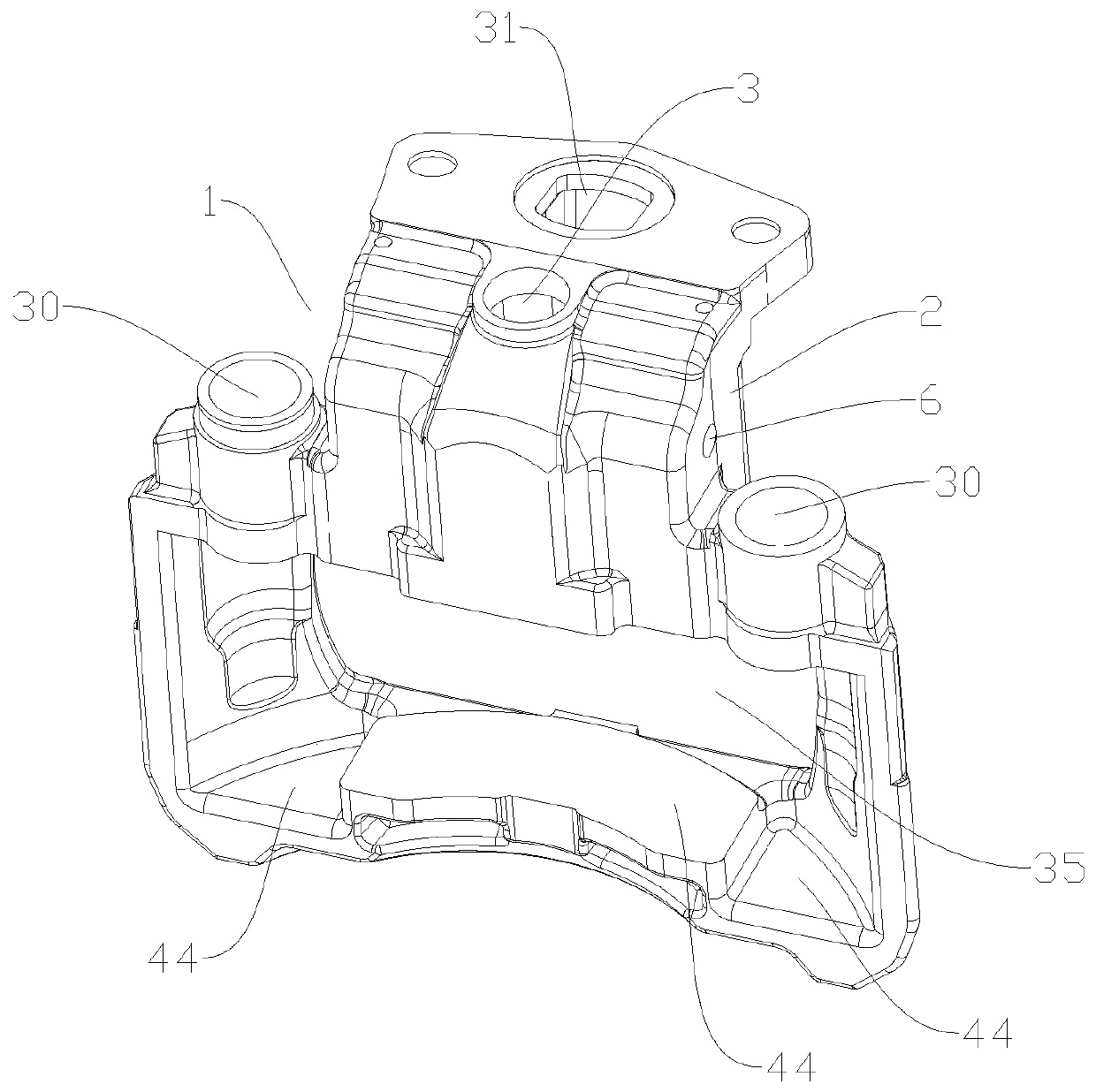
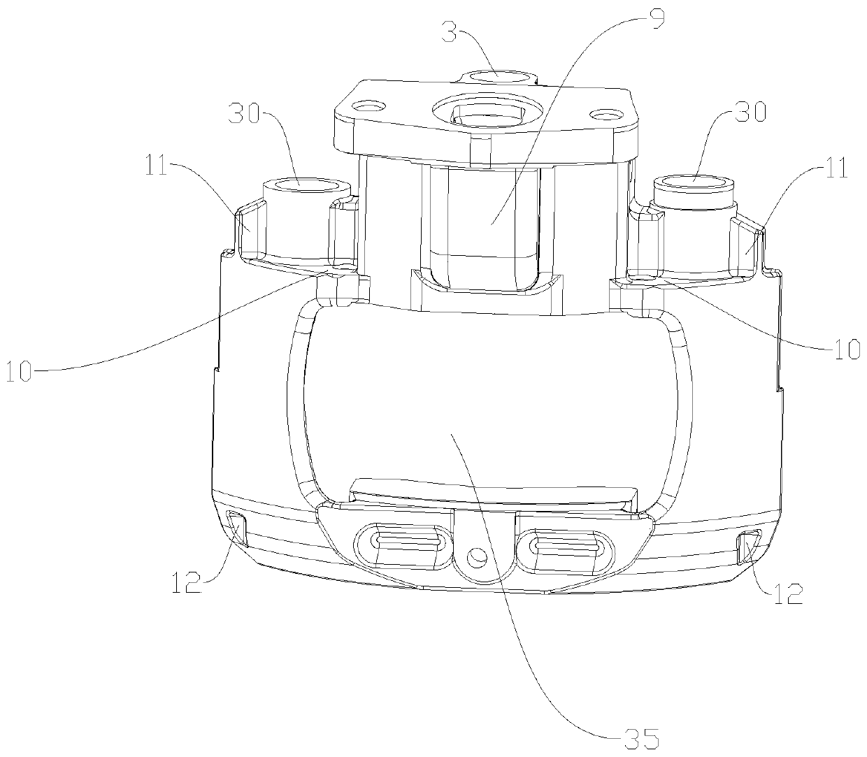
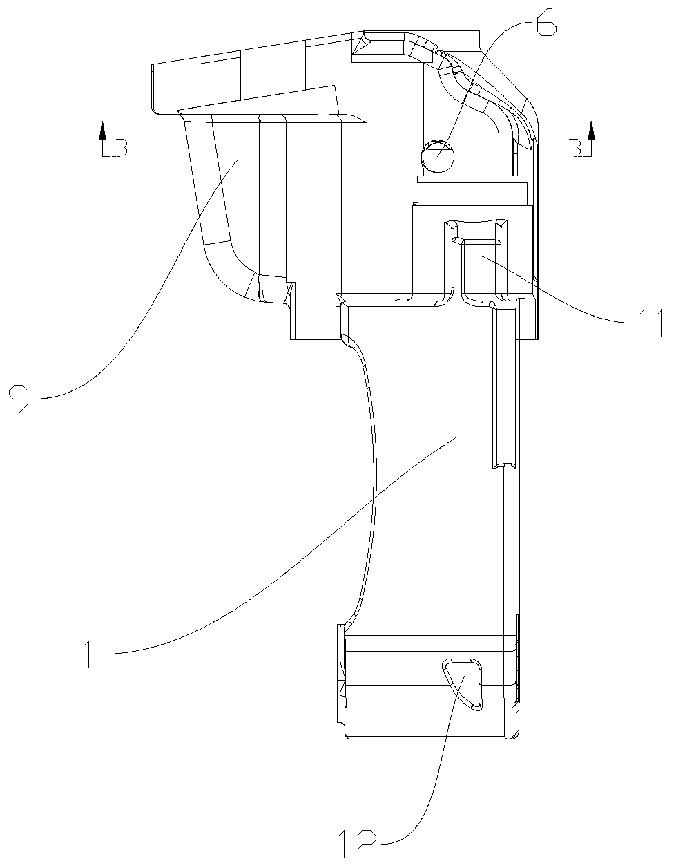
[0061] Such as Figure 1 to Figure 4 As shown, the present embodiment describes the structure of the caliper body 1 and the structure of the pneumatic disc brake equipped with the caliper body 1 . In this implementation, the brake is a single push rod type air disc brake. The pliers body 1 is integrally formed, and the pressure arm assembly installed in the pliers body 1 is integrally casted. The up, down, left, right, front and back directions of the following are figure 1 as the benchmark. The first assembly cavity 2 for assembling the pressure arm assembly is formed inside the caliper body 1. The upper end surface of the first assembly cavity 2 is provided with a shaft hole 3. The center of the shaft hole 3 is the braking center of the brake. When assembling, the adjuster assembly The adjusting rod of 17 is assembled in the axle hole 3. A force-receiving part 4 is formed in the first assembly cavity 2 , and the force-receiving part 4 is integrally formed as a boss exten...

Embodiment 2

[0080] This embodiment discloses a processing method for processing the pliers body 1 in the first embodiment.

[0081] First of all, it is necessary to limit the degrees of freedom of the caliper body 1 during the clamping process. The clamping process utilizes a horizontal machining center for processing. The first assembly cavity 2 comprises the second cavity 9 protruding to the back, the left and right sides of the first assembly cavity 2 are provided with a positioning platform 10, the height of the positioning platform 10 is less than the height of the upper end surface of the first assembly cavity 2, and the positioning platform 10 is formed with a pin hole 30, and the outside of the pin hole 30 is provided with a positioning shoulder 11, and the positioning shoulder 11 is integrally formed on the positioning table 10. In this embodiment, the pin hole 30 is a pipe fitting, and the pipe fitting and the pliers 1 is integrally formed, and a reinforcing rib is formed betwe...

Embodiment 3

[0094] The difference between this embodiment and Embodiment 1 is that: the process hole 6 is formed initially when the pliers body 1 is cast and formed, and then processed.


PUM


Abstract

The invention relates to the field of pneumatic disc brakes, and discloses a caliper body, a caliper body machining method and an assembly method of a brake with the caliper body. The caliper body isof an integrally-formed structure. A first assembly cavity is formed in the caliper body; a supporting frame is formed on the lower side of the first assembling cavity, pin holes are formed in the left side and the right side of the supporting frame, a shaft hole and a pressing hole are formed in the upper end face of the first assembling cavity, a stress part is formed in the first assembling cavity, a matching notch used for being matched with a rolling shaft is formed in the lower end face of the stress part, and the axis of the matching notch is perpendicular to that of the shaft hole; a process hole is formed in the side face of the first assembling cavity, and the projection of the matching notch in the extending direction of the matching notch falls into a projection area of the process hole in the axis direction of the matching notch. The brake has the advantages of being reliable in braking, easy to machine and high in production efficiency. Moreover, the caliper body is simple to process, and other parts are convenient to assemble.

Description

technical field [0001] The invention relates to the field of pneumatic disc brakes, in particular to a caliper body, a processing method for the caliper body, and a brake assembly method with the caliper body. Background technique [0002] At present, there are many kinds of pneumatic disc brakes on the market. If they are classified according to the driving method, they can be divided into single push rod pneumatic disc brakes and double push rod pneumatic disc brakes. Double push rod pneumatic disc brakes can also be divided into axial Air pressure disc brakes and radial air pressure disc brakes, if classified according to the assembly method of the rotating components, can be divided into upper cover type air pressure disc brakes and non-over cover type air pressure disc brakes. The non-cover type pneumatic disc brake is mainly an axial double-push rod pneumatic disc brake. Basically, the rotating components are in the form of small assemblies. The bottom cover, sealing ...

Claims


Application Information

Patent Timeline
Patent Type & Authority Applications(China)
IPC IPC(8): F16D65/00B23P15/00B23P21/00
CPCB23P15/00B23P21/00F16D65/0068F16D2055/0016
Inventor 王语风陆由南傅炎木吴涛张开年
Owner ZHEJIANG VIE SCI & TECH
Why Eureka
Try Eureka