Vision-based rotating light tracking type solar panel device

A solar panel and visual tracking technology, used in solar thermal energy, solar thermal power generation, solar thermal collectors, etc., can solve the problems of inability to achieve light tracking effect, change in measurement accuracy, harsh installation environment, etc., to achieve low-cost solar tracking, Good wind resistance, stable and compact structure

Pending Publication Date: 2020-04-10
SHANGHAI UNIVERSITY OF ELECTRIC POWER
View PDF0 Cites 5 Cited by
  • Summary
  • Abstract
  • Description
  • Claims
  • Application Information

AI Technical Summary

Problems solved by technology

[0007] However, the traditional solar tracker has some disadvantages: due to the functional limitations of the solar tracker, its installation environment is relatively harsh, and it needs to withstand the variable outdoor temperature, wind, frost, rain and snow. The traditional light intensity sensor is relatively simple and only has the sensor function. When the temperature changes, the measurement accuracy will change great

Method used


Image

  • Vision-based rotating light tracking type solar panel device
  • Vision-based rotating light tracking type solar panel device
  • Vision-based rotating light tracking type solar panel device

Examples


Embodiment

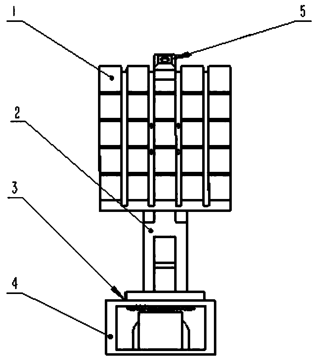
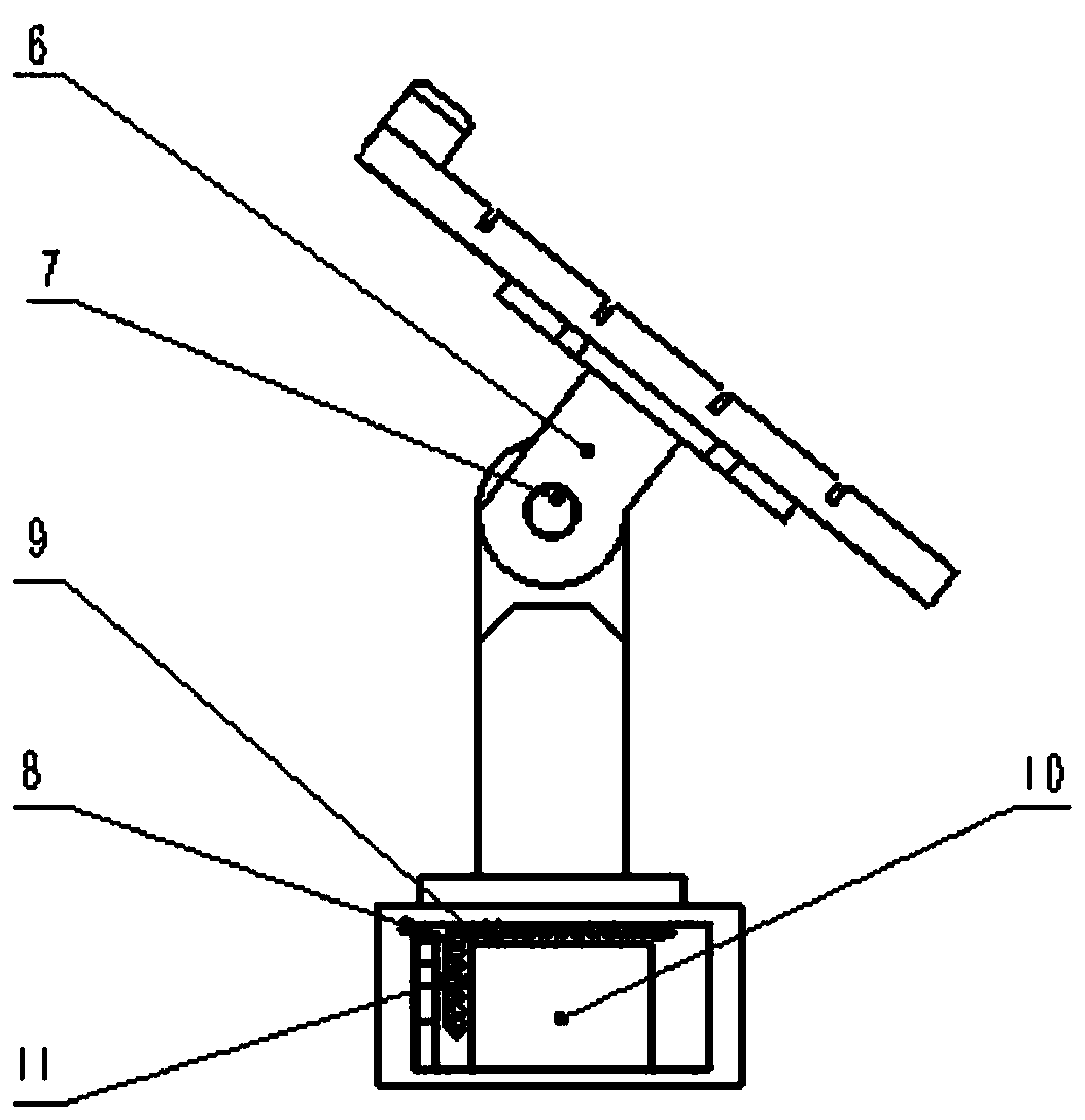
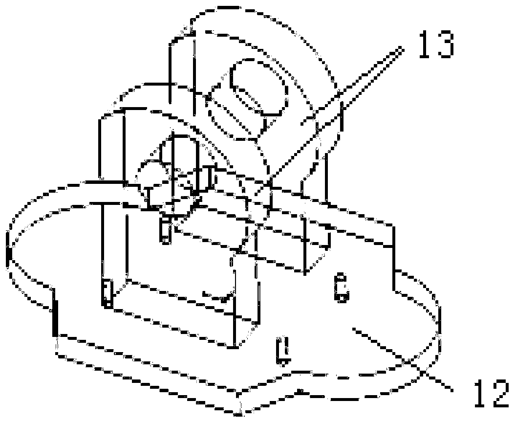
[0029] Such as Figure 1~3 As shown, a vision-based rotating and tracking solar panel device includes a base 4 and a solar panel 1 mounted on the base 4. The device also includes a horizontal rotation mechanism, a vertical pitch mechanism, a visual tracking mechanism and a control The horizontal rotation mechanism is installed on the base 4 and can rotate in the horizontal direction relative to the base 4. The vertical pitch mechanism is movably installed on the top of the horizontal rotation mechanism, and the vertical pitch mechanism can be vertical relative to the horizontal rotation mechanism. The solar panel 1 is fixed on the vertical tilt mechanism, and the visual tracking mechanism is installed on the solar panel 1 to track the center of the sun. The horizontal rotation mechanism, the vertical tilt mechanism and the visual tracking mechanism are all connected to the controller. Including microcontroller.

[0030] Specifically: the horizontal rotating mechanism includes a ...


PUM


Abstract

The invention relates to a vision-based rotating light tracking type solar panel device, which comprises a base (4) and a solar panel (1) mounted on the base (4), and further comprises a horizontal rotating mechanism, a vertical pitching mechanism, a visual tracking mechanism and a controller. The horizontal rotating mechanism is mounted on the base (4) and can make rotating motion in the horizontal direction relative to the base (4), the vertical pitching mechanism is movably mounted at the top of the horizontal rotating mechanism and can make pitching motion in the vertical direction relative to the horizontal rotating mechanism, the solar panel (1) is fixed to the vertical pitching mechanism, the visual tracking mechanism is mounted on the solar panel (1) and used for tracking the sun center, and the horizontal rotating mechanism, the vertical pitching mechanism and the visual tracking mechanism are all connected to the controller. Compared with the prior art, the structure is simple and reliable, and the power generation effect is high.

Description

Technical field [0001] The invention relates to a solar panel device, in particular to a vision-based rotating chasing solar panel device. Background technique [0002] The incoming solar radiation (sunlight) from the Earth in the upper atmosphere received 174 petawatts (PW). Approximately 30% of the solar energy is reflected back to space, while the remaining solar energy is absorbed by clouds, oceans and land. The solar energy spectrum on the earth's surface is mostly distributed in a small part of the near ultraviolet, all visible light, and near infrared spectrum. [0003] The solar energy absorbed by the earth’s atmosphere, oceans and land is approximately 3,850,000 EJ per year. In 2002, there was more solar energy in one hour than the world used in one year. The biomass energy obtained from photosynthesis is about 3000 EJ per year. The technical potential of biomass energy is 100-300 EJ / year. The amount of the sun’s energy reaching the surface of the earth is so huge tha...

Claims


Application Information

Patent Timeline
IPC IPC(8): F24S50/20F24S30/48H02S20/32
CPCF24S30/48F24S50/20H02S20/32Y02E10/47Y02E10/50
Inventor 王道累李明山季沛张天宇孙嘉珺李敏
Owner SHANGHAI UNIVERSITY OF ELECTRIC POWER
Why Eureka
Try Eureka