FP cavity adjustable filter

A filter, a pair of technology, used in instruments, optical components, optics, etc., can solve the problems of difficult to guarantee the uniformity of the cavity length, the deterioration of the high-power laser damage resistance, and the large aperture, so as to ensure the filtering performance. , The effect of ensuring uniformity and reducing the error of cavity length

Active Publication Date: 2020-04-10
EZHOU INST OF IND TECH HUAZHONG UNIV OF SCI & TECH +1
View PDF11 Cites 2 Cited by
  • Summary
  • Abstract
  • Description
  • Claims
  • Application Information

AI Technical Summary

Problems solved by technology

[0004] The purpose of the present invention is to overcome the deficiencies of the above-mentioned technologies, and propose a FP-cavity tunable filter to solve the problem that the FP-cavity tunable filter in the prior art is difficult to e

Method used


Image

  • FP cavity adjustable filter
  • FP cavity adjustable filter
  • FP cavity adjustable filter

Examples


Embodiment Construction

[0015] In order to make the object, technical solution and advantages of the present invention clearer, the present invention will be further described in detail below in conjunction with the accompanying drawings and embodiments. It should be understood that the specific embodiments described here are only used to explain the present invention, not to limit the present invention.

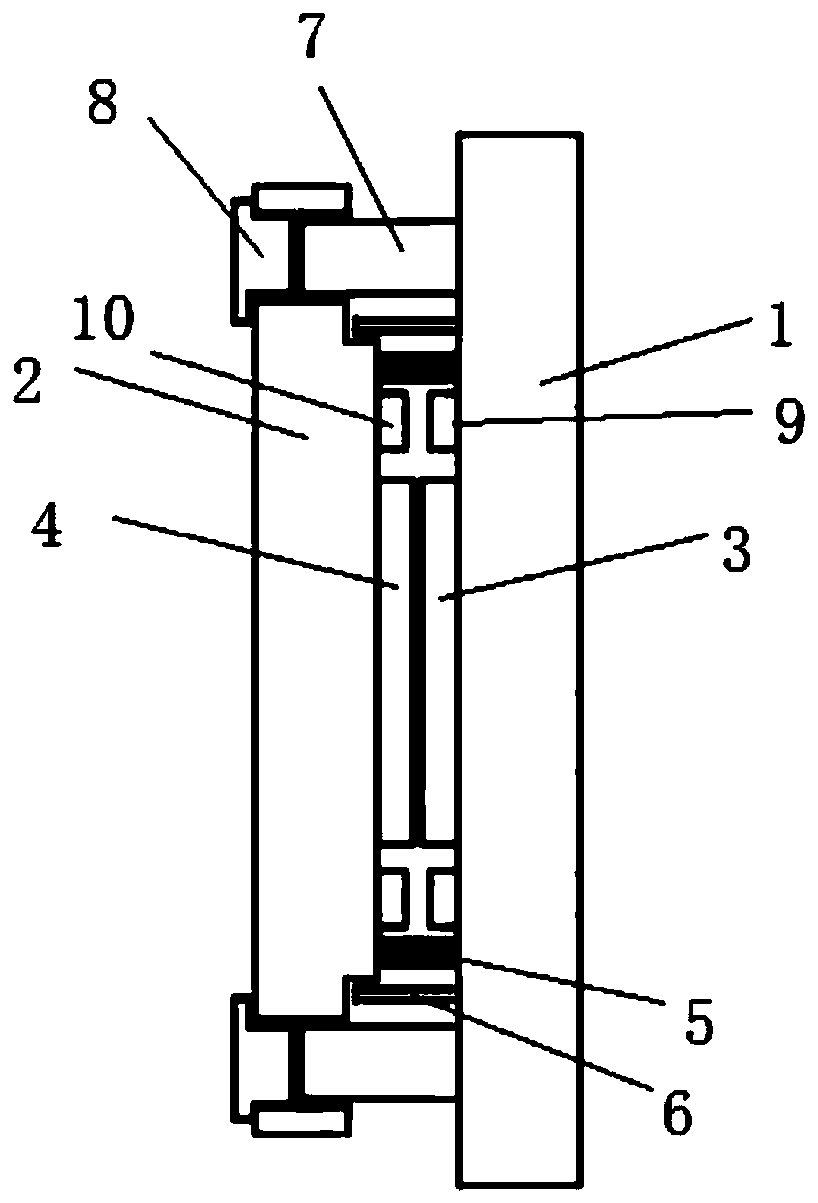
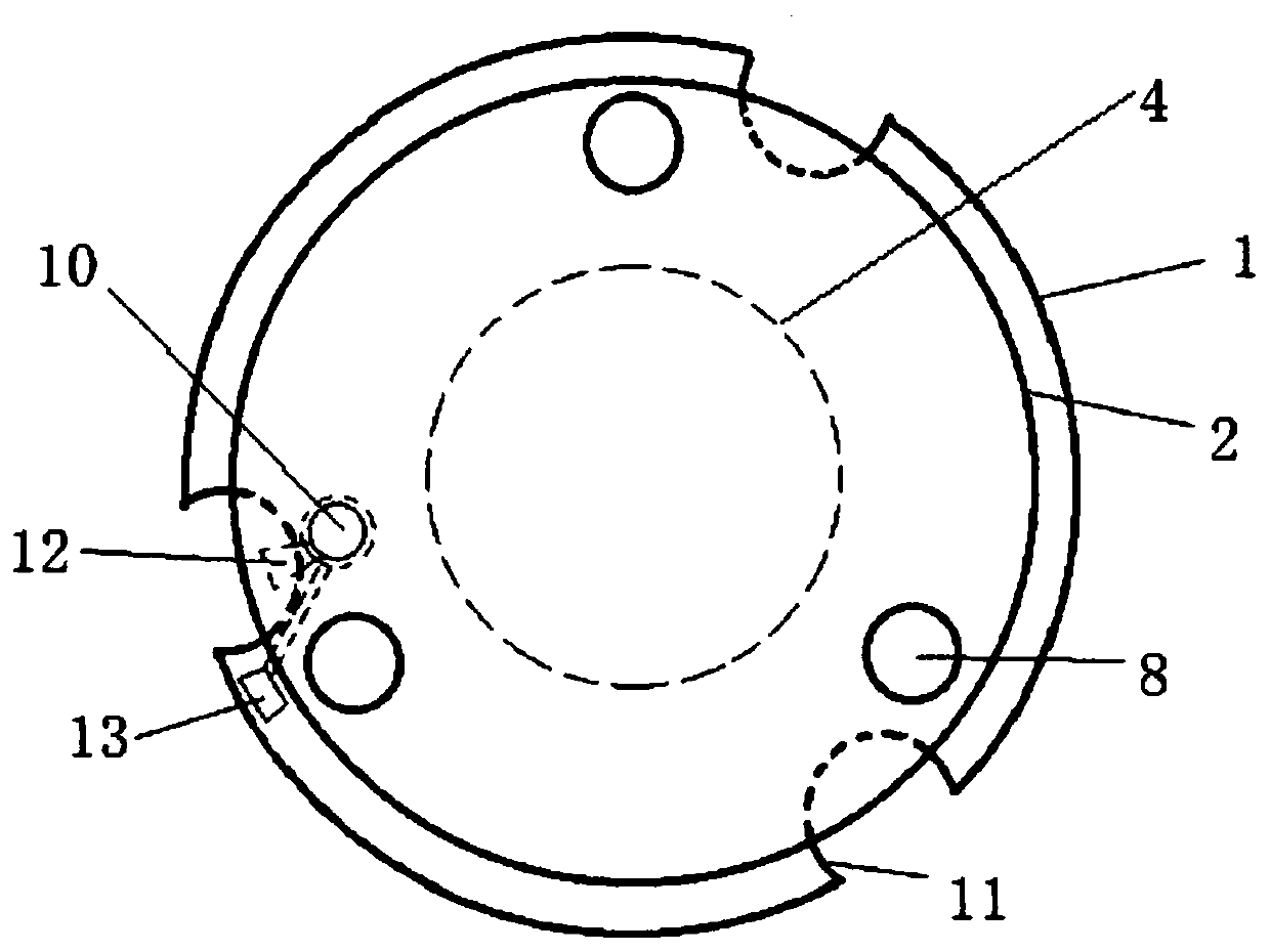
[0016] like figure 1 and figure 2 As shown, a PF cavity tunable filter includes a pair of spaced apart and parallel first flat plate 1 and second flat plate 2, and the two opposite surfaces of the first flat plate 1 and second flat plate 2 are plated respectively There are a first reflective film 3 and a second reflective film 4, an FP cavity is formed between the first reflective film 3 and the second reflective film 4, wherein the width between the first reflective film 3 and the second reflective film 4 Refers to the cavity length of the FP cavity. The thicknesses of the first flat plate 1 a...


PUM

PropertyMeasurementUnit
Thicknessaaaaaaaaaa

Abstract

The invention discloses an FP cavity adjustable filter, which comprises a pair of a first flat plate and a second flat plate which are mutually spaced and parallel. A plurality of isolation piles withthe same height are uniformly spaced at the peripheral position of a first reflecting film on the first flat plate; a plurality of piezoelectric ceramics are further fixedly installed on the peripheries of the isolation piles, the bottoms of the piezoelectric ceramics are fixedly connected to the first flat plate, and the tops of the piezoelectric ceramics are free ends; through holes are formedat positions right opposite to the piezoelectric ceramics on the second flat plate, the tops of the piezoelectric ceramics are inserted into the through holes; compensation blocks are further fixedlyinstalled on the second flat plate, one ends of the compensation blocks are fixedly connected to the second flat plate, and the other ends of the compensation blocks are inserted into the through holes and in contact with the tops of the piezoelectric ceramics, and the problems that the cavity length uniformity of an existing FP cavity adjustable filter is difficult to guarantee and the damage resistance is poor are solved.

Description

technical field [0001] The invention relates to the field of optoelectronic equipment, and more specifically, to an FP cavity tunable filter. Background technique [0002] Infrared tunable filters can flexibly select the required infrared spectral components from the infrared wide spectrum for detection or analysis. Application prospect. Due to the use of electrical signals for tuning, it has the characteristics of fast selection speed and flexible selection mode. It can work in single-point, continuous scanning, random scanning and multi-point modes. It is suitable for multi-spectral imaging and hyperspectral imaging. The existing infrared tunable filters include acousto-optic filters, liquid crystal filters and FP cavity filters, among which the FP cavity filter has the advantages of simple structure, large aperture, high spectral resolution and optical The characteristic of high efficiency has been used in frequency selection of lasers and ultra-narrow-band tunable filt...

Claims


Application Information

Patent Timeline
IPC IPC(8): G02B26/00
CPCG02B26/00
Inventor 赖建军谭云鹏远志昊
Owner EZHOU INST OF IND TECH HUAZHONG UNIV OF SCI & TECH
Why Eureka
Try Eureka