
Magnetic type electromagnetic induction demonstration instrument

An electromagnetic induction and magnetic suction technology, applied in the direction of instruments, educational appliances, teaching models, etc., can solve the problems of difficult induction current, difficult to move, large size, etc., and achieve the effect of reducing impact, reducing resistance, and simple and intuitive structure.

Pending Publication Date: 2020-04-10
TIANJIN SINO GERMAN VOCATIONAL TECHNICAL COLLEGE +1
View PDF0 Cites 0 Cited by
  • Summary
  • Abstract
  • Description
  • Claims
  • Application Information

AI Technical Summary

Problems solved by technology

However, several electromagnetic induction experiments listed in the chapter of electromagnetic induction in the middle school textbook are very simple. Although the effect is obvious, they cannot demonstrate the quantitative relationship between the induced current, the magnetic field, and the speed very well, causing students to struggle in understanding the induced current. It is very difficult to generate conditions
[0003] At present, there are many experimental instruments for demonstrating electromagnetic induction phenomena on the market, but there are still some problems with these instruments. Some of these instruments are too large to be easily moved, and it is not easy to demonstrate them in theoretical classrooms; although some have obvious effects, they can only be used on the platform In the demonstration, the students at the back of the classroom are not easy to observe; some can demonstrate the experiment, but they cannot demonstrate the quantitative relationship between the induced current, magnetic flux and time well

Method used


Image

  • Magnetic type electromagnetic induction demonstration instrument
  • Magnetic type electromagnetic induction demonstration instrument

Examples


Embodiment Construction

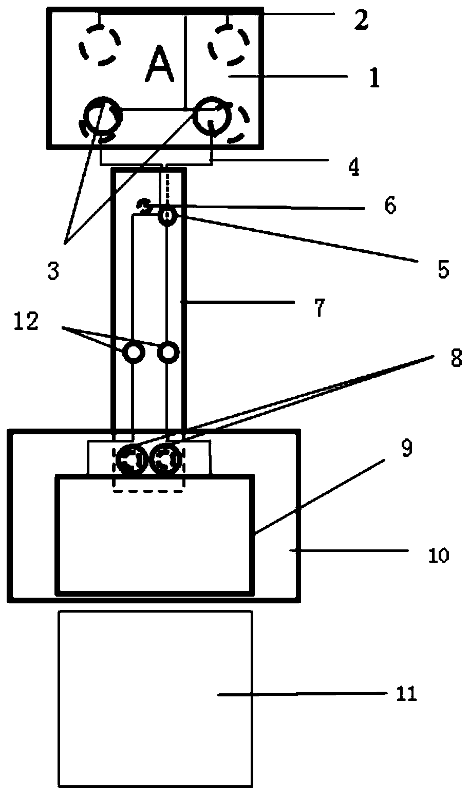
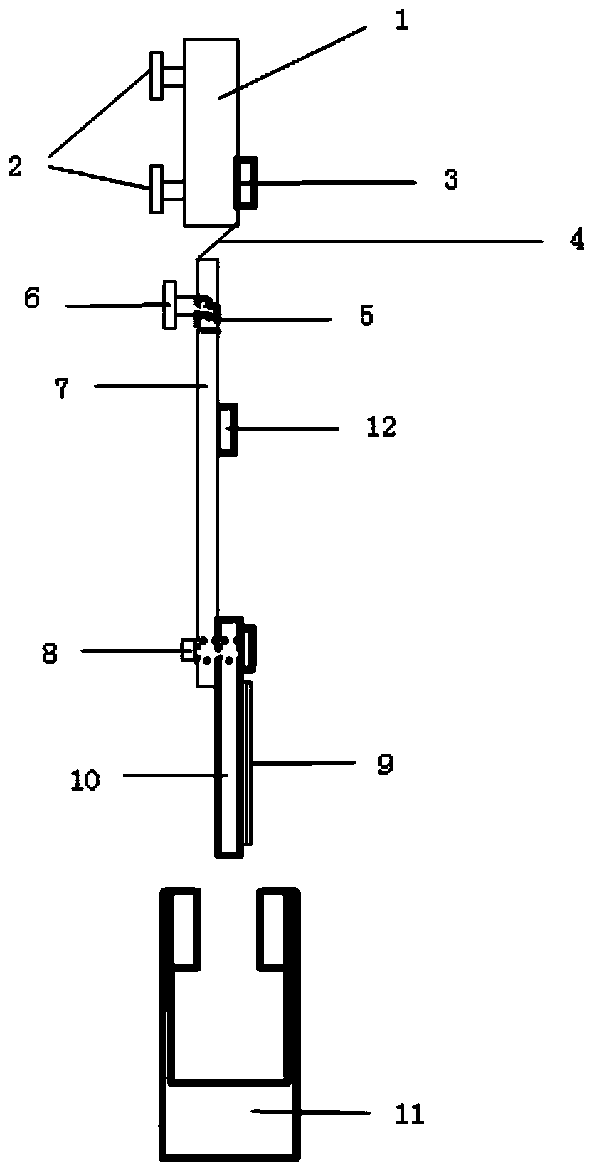
[0019] The specific implementation manner of the present invention will be described in detail below in conjunction with the accompanying drawings and preferred embodiments. Such as figure 1 As shown, a magnetic induction demonstration instrument includes a galvanometer 1, a bottom plate magnet 2, a first terminal post 3, a flexible wire 4, a small hole 5, a magnetic shaft 6, a first acrylic plate 7, and a screw 8. Coil 9, second acrylic plate 10, strong U-shaped magnet 11 and second terminal 12; the galvanometer 1 is a common galvanometer in the laboratory, and the four corners on the back of the galvanometer 1 are equipped with Four bottom plate magnets 2, the main function of these four floor magnets is to adsorb the galvanometer on the blackboard; there are two first terminal posts 3 on the front of the galvanometer; There is a small hole drilled in the upper part, and a magnetic shaft is installed next to the small hole (the main function is to attract the acrylic board ...


PUM


Abstract

The invention relates to the technical field of electromagnetic teaching demonstration devices, and in particular, relates to a magnetic type electromagnetic induction demonstration instrument comprising a galvanometer, bottom plate magnets, first binding posts, a flexible wire, a magnetic type shaft, a first acrylic plate, screws, a coil, a second acrylic plate, a strong U-shaped magnet and second binding posts; four bottom plate magnets are arranged at four corners of the back surface of the galvanometer; two first binding posts are arranged on the front surface of the galvanometer; the upper half part of the first acrylic plate is provided with the magnetic type shaft, and the middle part of the first acrylic plate is provided with the two second binding posts respectively; the coil isfixed on the second acrylic plate, and the two screws are respectively arranged at the upper half part of the second acrylic plate; the first binding posts are connected with the second binding poststhrough the flexible wire, and the coil is connected with the second binding posts; and the strong U-shaped magnet is attracted on the blackboard to provide a magnetic field for an experiment. The demonstration instrument is simple and visual in structure and convenient for demonstrating the principle of the electromagnetic induction law.

Description

technical field [0001] The invention relates to the technical field of electromagnetic teaching demonstration devices, in particular to a magnetic suction type electromagnetic induction demonstration device. Background technique [0002] Electromagnetism is a major difficulty in high school physics. To learn electromagnetism well, it is very important to understand the law of electromagnetic induction. Physics is a science based on experiments, and experiments related to it are particularly important for students to understand the law of electromagnetic induction. However, several electromagnetic induction experiments listed in the chapter of electromagnetic induction in the middle school textbook are very simple. Although the effect is obvious, they cannot demonstrate the quantitative relationship between the induced current, the magnetic field, and the speed very well, causing students to struggle in understanding the induced current. It is very difficult to generate cond...

Claims


Application Information

Patent Timeline
IPC IPC(8): G09B23/18
CPCG09B23/181
Inventor 杨广武王慧华
Owner TIANJIN SINO GERMAN VOCATIONAL TECHNICAL COLLEGE
Learn More