Automatic correction method for excimer laser annealing process OED

An excimer laser and automatic correction technology, which is applied in semiconductor/solid-state device manufacturing, image data processing, instruments, etc., can solve the problems of tediousness, inconvenient implementation, and low correction accuracy, so as to achieve accurate data and reduce product quality deviation , Ease of use

Pending Publication Date: 2020-04-10
信利(仁寿)高端显示科技有限公司
View PDF13 Cites 0 Cited by
  • Summary
  • Abstract
  • Description
  • Claims
  • Application Information

AI Technical Summary

Problems solved by technology

This correction technology is basically completed by manual operation, which has many shortcomings such as cumbersome, inconvenient implementation, and low correction accuracy.

Method used


Image

  • Automatic correction method for excimer laser annealing process OED
  • Automatic correction method for excimer laser annealing process OED
  • Automatic correction method for excimer laser annealing process OED

Examples


Embodiment 1

[0084] An automatic correction method for an excimer laser annealing process OED, comprising the steps of:

[0085] Using an excimer laser annealing device to convert the amorphous silicon on the surface of the substrate into polysilicon; using the Mura quantification method to obtain the real-time Mura value of the substrate, and report the Mura value to the control system;

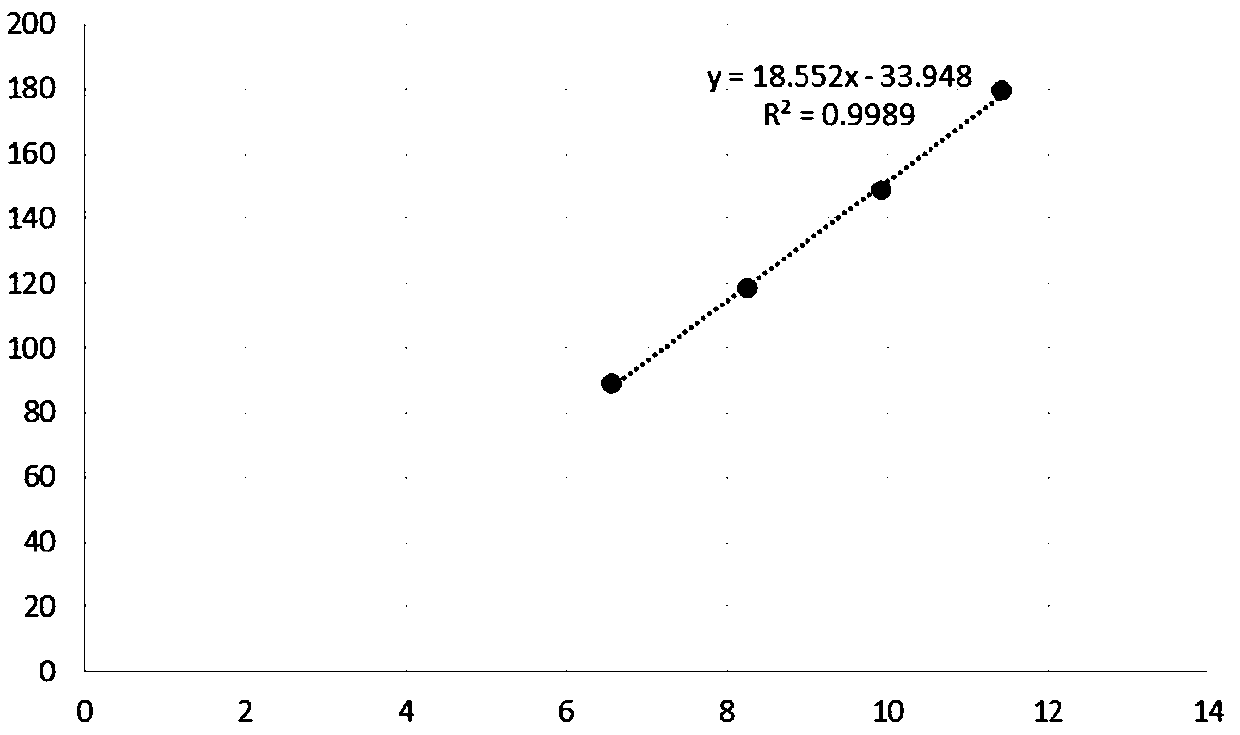
[0086] The control system compares the Mura value with the preset Mura value range, and if the Mura value exceeds the preset Mura value range, the control system controls the excimer laser annealing device to correct the optimal energy density, wherein The method of correcting the optimal energy density is: (1) provide a substrate with an amorphous silicon layer on the surface, and the amorphous silicon layer is divided into multiple regions; (2) perform excimer laser annealing, and use different energies respectively Density excimer laser irradiates each area; (3) Use the Mura quantification method to q...

Embodiment 2

[0098] An automatic correction method for an excimer laser annealing process OED, comprising the steps of:

[0099] Using an excimer laser annealing device to convert the amorphous silicon on the surface of the substrate into polysilicon; using the Mura quantification method to obtain the real-time Mura value of the substrate, and report the Mura value to the control system;

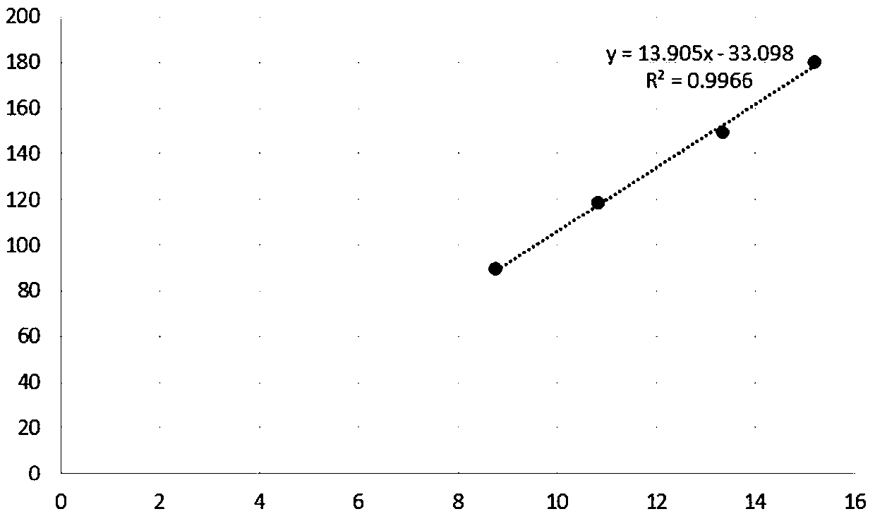
[0100] The control system compares the Mura value with the preset Mura value range, and if the Mura value exceeds the preset Mura value range, the control system controls the excimer laser annealing device to correct the optimal energy density, wherein The method of correcting the optimal energy density is: (1) provide a substrate with an amorphous silicon layer on the surface, and the amorphous silicon layer is divided into multiple regions; (2) perform excimer laser annealing, and use different energies respectively Density excimer laser irradiates each area; (3) Use the Mura quantification method to q...


PUM


Abstract

The invention discloses an automatic correction method for an excimer laser annealing process OED, which does not need manual operation, is convenient to implement, reliable in performance, efficientand accurate, and comprises the following steps: acquiring a real-time Mura value by adopting a Mura quantification method, and reporting the Mura value to a control system; comparing the Mura value with a preset Mura value range, if the Mura value exceeds the preset Mura value range, controlling the excimer laser annealing device to correct the optimal energy density. The correction method comprises the steps that (1) a substrate with an amorphous silicon layer on the surface is provided, and the amorphous silicon layer is divided into a plurality of areas; (2) excimer lasers with different energy densities are used for irradiating all the areas respectively; (3) the Mura value of each region is quantified by adopting a Mura quantification method, wherein the energy density of the excimerlaser corresponding to the region with the minimum Mura value is the optimal energy density; and (4) the product substrate with the amorphous silicon layer is irradiated by the excimer laser annealing device through the excimer laser with the optimal energy density.

Description

technical field [0001] The invention relates to the field of display technology, in particular to an automatic correction method of an excimer laser annealing process OED. Background technique [0002] Low Temperature Polysilicon (LTPS) thin film due to its regular arrangement of atoms and high carrier mobility (10-300cm2 / Vs), when applied to other electronic components, can make TFT have a higher drive current, Therefore, the LTPS film is widely used as the material of the active layer, one of the core structures of the TFT, in the manufacturing process of the TFT. At present, in the modern TFT manufacturing process, the method of Excimer laser annealing (ELA) is mostly used to form the polysilicon active layer. Among them, the ELA method mainly irradiates the amorphous silicon thin film with an excimer laser with a certain energy density, and uses the energy of the laser beam to transform the amorphous silicon into LTPS at high temperature. The polysilicon TFT formed by ...

Claims


Application Information

Patent Timeline
Patent Type & Authority Applications(China)
IPC IPC(8): H01L21/268H01L21/66G06T5/00
CPCH01L21/268H01L22/12H01L22/20G06T5/001
Inventor 杨曲周波马春华林锦辉
Owner 信利(仁寿)高端显示科技有限公司
Why Eureka
Try Eureka