Mura quantification method based on excimer laser annealing

A technology of excimer laser and quantification method, which is applied in the quantification field of Mura, can solve the problems of human eye fatigue, strong subjectivity, and different manual judgment standards, and achieve the effect of reducing product quality deviation

Pending Publication Date: 2020-04-10
信利(仁寿)高端显示科技有限公司
View PDF16 Cites 0 Cited by
  • Summary
  • Abstract
  • Description
  • Claims
  • Application Information

AI Technical Summary

Problems solved by technology

However, due to the instability of the laser energy used and the inhomogeneity of the energy at different positions of the beam, the obtained polysilicon crystallization rate, grain size and internal defect density will be different.
These differences are closely related to the threshold voltage (Vth) and mobility of TFTs, and when reflected in OLED displays, uneven luminance (Mura) will appear
[0003] At present, most of the Mura inspections based on excimer laser annealing are not out of the manual inspection stage, and trained workers directly observe to determine whether the display panel has uneven brightness defects
However, due to the high cost of manual inspection and the long inspection time, only sampling inspections can be carried out, and the manual judgment standards are different, and there is no unified quantitative standard for judgment. Eye fatigue, these shortcomings have become important problems that limit the production efficiency of the production line and the improvement of detection accuracy
At the same time, the accuracy of manual detection is uncontrollable, the reliability is relatively low, and the efficiency is low

Method used


Image

  • Mura quantification method based on excimer laser annealing
  • Mura quantification method based on excimer laser annealing
  • Mura quantification method based on excimer laser annealing

Examples


Embodiment 1

[0054] A method for quantifying Mura based on excimer laser annealing, comprising the steps of:

[0055] S1. Under different light intensities, collect Mura images of the same area of ​​the same substrate after excimer laser annealing;

[0056] S2. carry out image processing to described Mura image by picture processing software, obtain the gray scale intensity of each pixel, the area recognition of gray scale intensity less than preset threshold value is Mura area, otherwise identify as non-Mura area; Through picture processing software The grayscale intensity of the pixels in the Mura area is changed to 0, and the grayscale intensity of the pixels in the non-Mura area is changed to 255 to determine the area of ​​the Mura area;

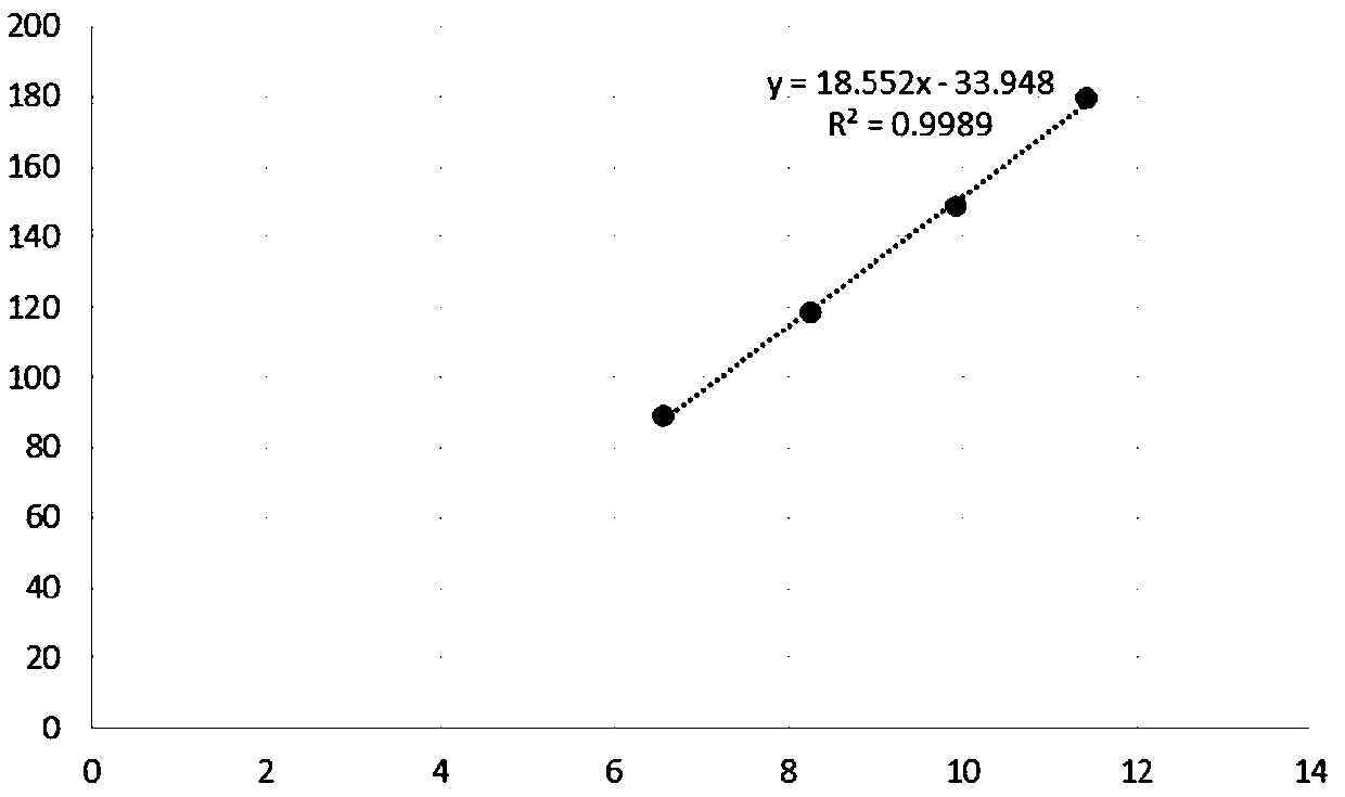
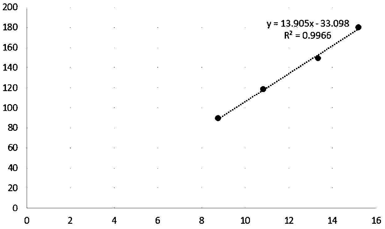
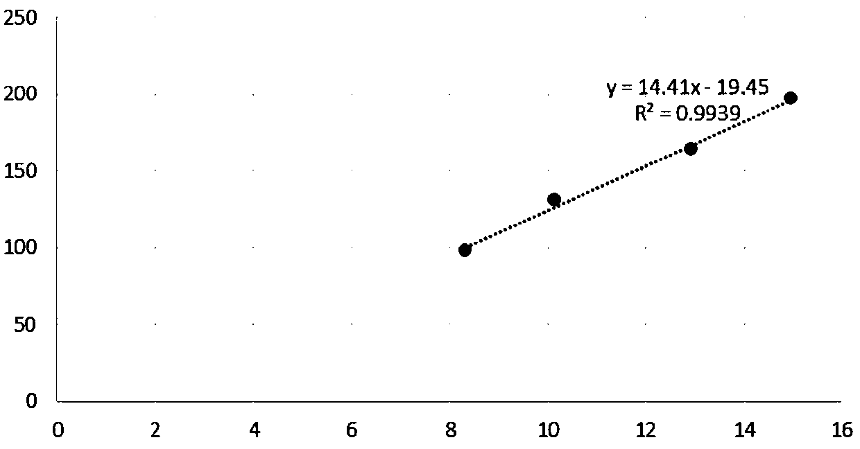
[0057] S3. With the light intensity as the ordinate and the area of ​​the Mura area as the abscissa, multiple data points are used for linear regression fitting to obtain the first linear relationship curve between the light intensity and the area of...


PUM


Abstract

The invention discloses a Mura quantification method based on excimer laser annealing. The method comprises the following steps of: S1, respectively collecting Mura images of the same region of the same substrate after excimer laser annealing under different light intensities, S2, performing image processing on the Mura image, and determining the area of a Mura region, S3, drawing a linear relation curve between the light intensity and the area of the Mura region, S4, repeating the steps S1-S3, and enabling each linear relation curve drawn in the same coordinate system to pass through a G point, S5, acquiring a Mura image of a selected region of the to-be-detected substrate under a certain light intensity, and processing the Mura image to obtain the area of the Mura region of the to-be-detected substrate, and drawing a point A in the coordinate system according to the light intensity and the area of the Mura region, S6, connecting the point G and the point A to obtain a straight line,and calculating the slope of the straight line, and S7, carrying out Mura quantization on the selected region by adopting the slope or the reciprocal of the slope. According to the method, the qualityof the polycrystalline silicon after the excimer laser annealing process can be quantitatively judged, and the defect of subjective feeling evaluation of human eyes is overcome.

Description

technical field [0001] The invention relates to the field of display technology, in particular to a method for quantifying Mura based on excimer laser annealing. Background technique [0002] Low Temperature Polysilicon (LTPS) thin film due to its atomic arrangement rules, high carrier mobility (10-300cm2 / Vs), when used in other electronic components, can make TFT have a higher drive current, Therefore, the LTPS film is widely used as the material of the active layer, one of the core structures of the TFT, in the manufacturing process of the TFT. At present, in the modern TFT manufacturing process, the method of Excimer laser annealing (ELA) is mostly used to form the polysilicon active layer. Among them, the ELA method mainly irradiates the amorphous silicon film with a certain energy excimer laser, and uses the energy of the laser beam to transform the amorphous silicon into LTPS at high temperature. The polysilicon TFT formed by ELA has the advantage of high mobility. ...

Claims


Application Information

Patent Timeline
Patent Type & Authority Applications(China)
IPC IPC(8): G06F30/20
Inventor 杨曲周波马春华林锦辉
Owner 信利(仁寿)高端显示科技有限公司
Why Eureka
Try Eureka