
LED support manufacturing method and LED support

A technology for an LED bracket and a manufacturing method, which is applied to electrical components, circuits, semiconductor devices, etc., can solve the problems of destroying the silver layer, insufficient bonding force between terminals and plastic, and high cost of electroplating on the surface of terminals.

Active Publication Date: 2020-04-10
东莞智昊光电科技有限公司
View PDF4 Cites 2 Cited by
  • Summary
  • Abstract
  • Description
  • Claims
  • Application Information

AI Technical Summary

Problems solved by technology

The traditional manufacturing process of LED brackets is: stamping terminal→electroplating→injection molding→cutting feet→finished product. The disadvantages are: the hardware terminal is electroplated before injection molding, and the cost of electroplating the entire terminal surface is high; the mold core and electroplating in the injection molding process Terminal contact may damage the silver layer and affect the reflectivity; the surface finish of the silver-plated terminal is greater than that of the unplated terminal, so that the terminal has insufficient bonding force with the plastic, resulting in poor airtightness of the product

Method used


Image

  • LED support manufacturing method and LED support

Examples


Embodiment Construction

[0024] In order to facilitate the understanding of the present invention, the present invention will be described more fully below with reference to the associated drawings. Preferred embodiments of the invention are shown in the accompanying drawings. However, the present invention can be embodied in many different forms and is not limited to the embodiments described herein. On the contrary, these embodiments are provided to make the understanding of the disclosure of the present invention more thorough and comprehensive.

[0025] It should be noted that when an element is referred to as being “fixed” to another element, it can be directly on the other element or there can also be an intervening element. When an element is referred to as being "connected to" another element, it can be directly connected to the other element or intervening elements may also be present.

[0026] Unless otherwise defined, all technical and scientific terms used herein have the same meaning as...


PUM


Abstract

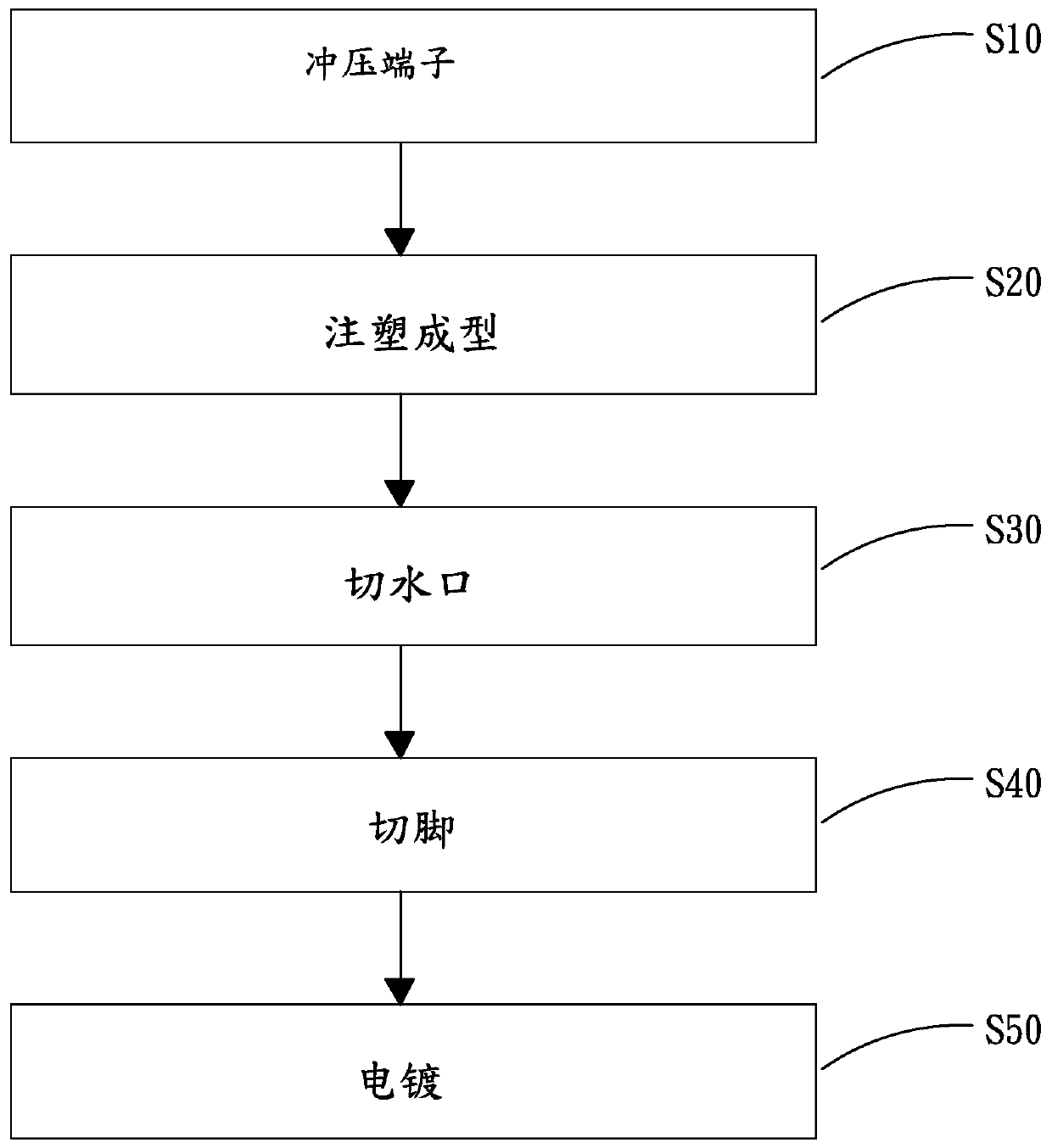
The invention relates to an LED support manufacturing method. The method comprises the following steps: stamping a terminal: stamping a metal material to obtain the metal terminal; performing injection molding; sealing the metal terminal in an injection mold, injecting a liquid thermosetting material into the injection mold, and heating the injection mold to cure and mold the thermosetting material on the metal terminal to obtain a plastic main body; cutting a water gap, namely, cutting the water gap on the plastic main body; pin cutting, namely, cutting the pin parts, and extending out of theplastic main body, of the metal terminals so as to trim the shape; and electroplating, namely, electroplating the surfaces of the metal terminals extending out of the plastic main body. The inventionfurther provides an LED support obtained through the LED support manufacturing method. The method has the beneficial effects that electroplating is carried out after injection molding and pin cutting, the electroplating area is reduced, the electroplating cost is reduced, a silver layer formed by electroplating is protected, the surface reflectance of the metal terminal is protected, the bindingforce of the metal terminal and plastic is improved, and the air tightness of a product is improved.

Description

technical field [0001] The invention relates to the technical field of LED production, in particular to a method for manufacturing an LED bracket and an LED bracket. Background technique [0002] LED (full name in English: Light Emitting Diode, Chinese name: Light Emitting Diode) is a common light-emitting device. Its working principle is to release energy and emit light through the recombination of electrons and holes. It is widely used in the field of lighting. LEDs can efficiently convert electrical energy into light energy, and have a wide range of uses in modern society, such as lamp lighting, display screens, medical devices, or various light indicating tools. At present, in the field of lamp lighting, LED chips are generally mounted on LED brackets to form LED lamps. [0003] LED brackets are generally injection-molded plastic bodies on metal terminals. The traditional manufacturing process of LED brackets is: stamping terminal→electroplating→injection molding→cutti...

Claims


Application Information

Patent Timeline
Patent Type & Authority Applications(China)
IPC IPC(8): H01L33/62H01L33/52H01L33/48
CPCH01L33/48H01L33/52H01L33/62H01L2933/0033H01L2933/005H01L2933/0066
Inventor 孙业民张永林刘泽陈文菁龙涛
Owner 东莞智昊光电科技有限公司
Learn More