A lithium battery cooling device for new energy vehicle batteries

A new energy vehicle and cooling device technology, applied in fuel cells, secondary batteries, regenerative fuel cells, etc., can solve the problem that the liquid cooling cooling system consumes the energy of the battery system, increases the volume and weight of the battery system, and reduces the energy density of the battery system. and other problems, to achieve the effect of improving heat dissipation, simple structure, and reducing volume and thickness

Active Publication Date: 2022-07-12
SOUTHWEST JIAOTONG UNIV
View PDF7 Cites 0 Cited by
  • Summary
  • Abstract
  • Description
  • Claims
  • Application Information

AI Technical Summary

Problems solved by technology

For this active liquid-cooled battery heat dissipation system, in order to achieve a good heat dissipation effect, a higher coolant flow rate and a lower coolant inlet temperature are required, which will inevitably greatly increase the energy consumption of the pump and refrigeration system
For electric vehicles, especially pure electric vehicles, the capacity of the battery system is limited and precious, so the liquid cooling system will consume a lot of energy in the battery system when it is running; in addition, the cooling system is a part of the battery system. Arranging liquid cold plates between them increases the volume and weight of the entire battery system, thereby reducing the overall energy density of the battery system

Method used


Image

  • A lithium battery cooling device for new energy vehicle batteries
  • A lithium battery cooling device for new energy vehicle batteries
  • A lithium battery cooling device for new energy vehicle batteries

Examples


Embodiment Construction

[0024] The technical solutions in the embodiments of the present invention will be clearly and completely described below with reference to the accompanying drawings in the embodiments of the present invention. Obviously, the described embodiments are only a part of the embodiments of the present invention, but not all of the embodiments. Based on the embodiments in the present invention, all other embodiments obtained by those of ordinary skill in the art fall within the protection scope of the present invention.

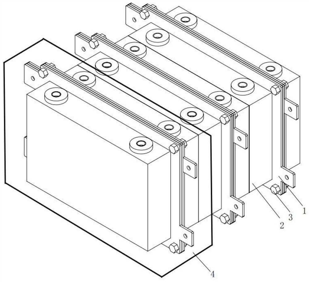
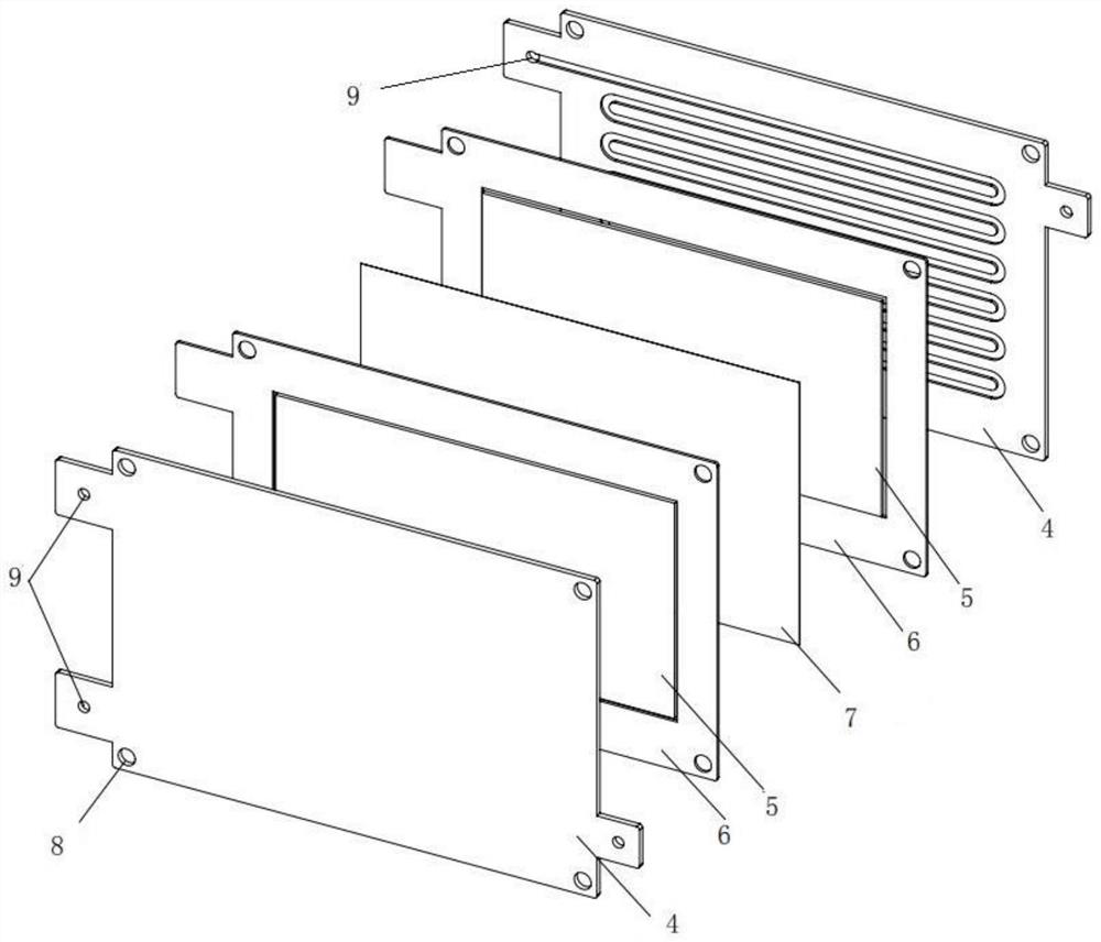
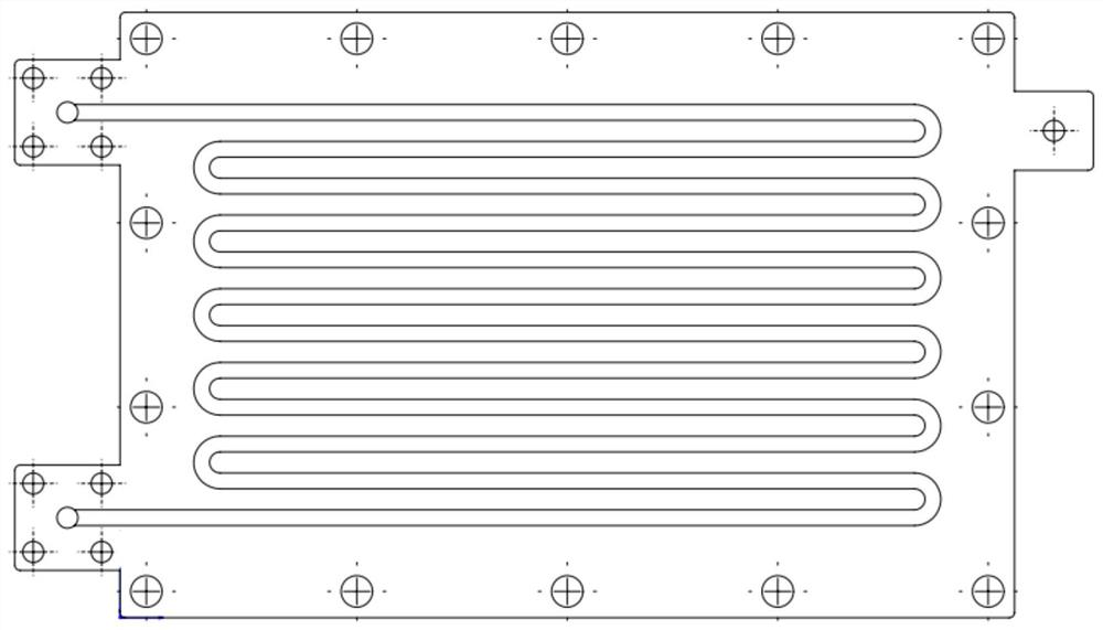
[0025] figure 1 The structure of a lithium battery cooling device for a new energy vehicle battery according to an embodiment of the present invention is shown. like Figure 1-Figure 3 As shown, an embodiment of the present invention is a lithium battery heat dissipation device for a new energy vehicle battery, including a flow battery cell 1 that can be used as a heat dissipation liquid cold plate after modification, a lithium battery 2 that is liquid-cooled and ...


PUM

PropertyMeasurementUnit
thicknessaaaaaaaaaa
thicknessaaaaaaaaaa

Abstract

The invention discloses a lithium battery cooling device for a new energy vehicle battery, comprising a flow battery cell which can be used as a cooling liquid cooling plate after transformation, a lithium battery subjected to liquid cooling and heat dissipation, and a flow battery cell for cooling the liquid flow battery cell. The connecting piece that connects the various parts of the body together; the flow battery cell is arranged between the lithium batteries in a clamping manner; the two lithium batteries and a clamped flow battery cell together constitute a minimum part of the lithium battery heat dissipation device. The heat dissipation unit; the flow battery unit includes a battery diaphragm in the middle, positive / negative flow field plates on the two most sides, positive / negative electrodes, and positive / negative electrode frames. The invention provides a lithium battery cooling device for a new energy vehicle battery, which adopts a flow battery cell structure with a large flow field area, a small overall thickness and a simple structure, and is applied to the lithium battery cooling device to realize heat dissipation. The device itself has the function of storing electricity, and at the same time, the volume and thickness of the device can be greatly reduced, and the heat dissipation effect can be improved.

Description

technical field [0001] The invention belongs to the technical field of heat dissipation devices, and in particular relates to a lithium battery heat dissipation device for new energy vehicle batteries. Background technique [0002] In the thermal management technology of lithium-ion power batteries for new energy vehicles, since the air-cooled heat dissipation often cannot meet the expected heat dissipation effect, a liquid-cooled battery heat dissipation system using liquid as the medium for thermal management of the power battery has been developed. The heat dissipation method is that the liquid medium flows through the battery and takes away the heat of the battery, and is transported to the heat exchanger by the pump for cooling, and the cooled fluid (cooling liquid) flows through the battery again. [0003] Because the square lithium-ion battery has a regular shape and a flat surface, the battery can be cooled by arranging a cooling liquid cold plate between adjacent si...

Claims


Application Information

Patent Timeline
Patent Type & Authority Patents(China)
IPC IPC(8): H01M16/00H01M10/613H01M10/625H01M10/647H01M10/6555H01M10/6568H01M8/18H01M10/0525
CPCH01M16/006H01M8/188H01M10/613H01M10/625H01M10/647H01M10/6555H01M10/6568H01M10/0525Y02E60/50Y02E60/10
Inventor 曾义凯陆飞
Owner SOUTHWEST JIAOTONG UNIV
Why Eureka
Try Eureka