Cloud splicing control method and system based on distributed network

A distributed network and control system technology, applied in the field of cloud splicing control methods and systems, can solve problems such as the inability to solve cross-regional multi-point distributed display control management problems, to improve quantity and quality, realize signal switching functions and point-to-point The effect of multi-transmission and extended transmission distance

Inactive Publication Date: 2020-04-10
东莞市九鼎实业有限公司
View PDF1 Cites 2 Cited by
  • Summary
  • Abstract
  • Description
  • Claims
  • Application Information

AI Technical Summary

Problems solved by technology

[0004] Compared with the prior art, the high-speed bus-based video transmission and processing method disclosed in the above invention completes data exchange in a hand-in-hand manner, without the need for complex video data exchange chips; the link is direct, without complicated signal processing, maintaining Signal integrity; there are dedicated video signal input and output modules, each module is a separate module, and each module can be upgraded independently, one architecture, all common; because there are dedicated video input and video output modules, the video signal Processing and transmission, can carry out targeted processing, individual modules have scalable computing power, and can perfectly process video signals; for capacity expansion, there is no need to change the hardware architecture, just connect a certain system with a home network cable, But it still has certain defects, because it still uses the traditional bus transmission method, there are always certain limitations, and it can not solve the control management problem of multi-point distributed display across regions

Method used


Image

  • Cloud splicing control method and system based on distributed network
  • Cloud splicing control method and system based on distributed network

Examples


Embodiment Construction

[0024] The following will clearly and completely describe the technical solutions in the embodiments of the present invention with reference to the accompanying drawings in the embodiments of the present invention. Obviously, the described embodiments are only some, not all, embodiments of the present invention. Based on the embodiments of the present invention, all other embodiments obtained by persons of ordinary skill in the art without making creative efforts belong to the protection scope of the present invention.

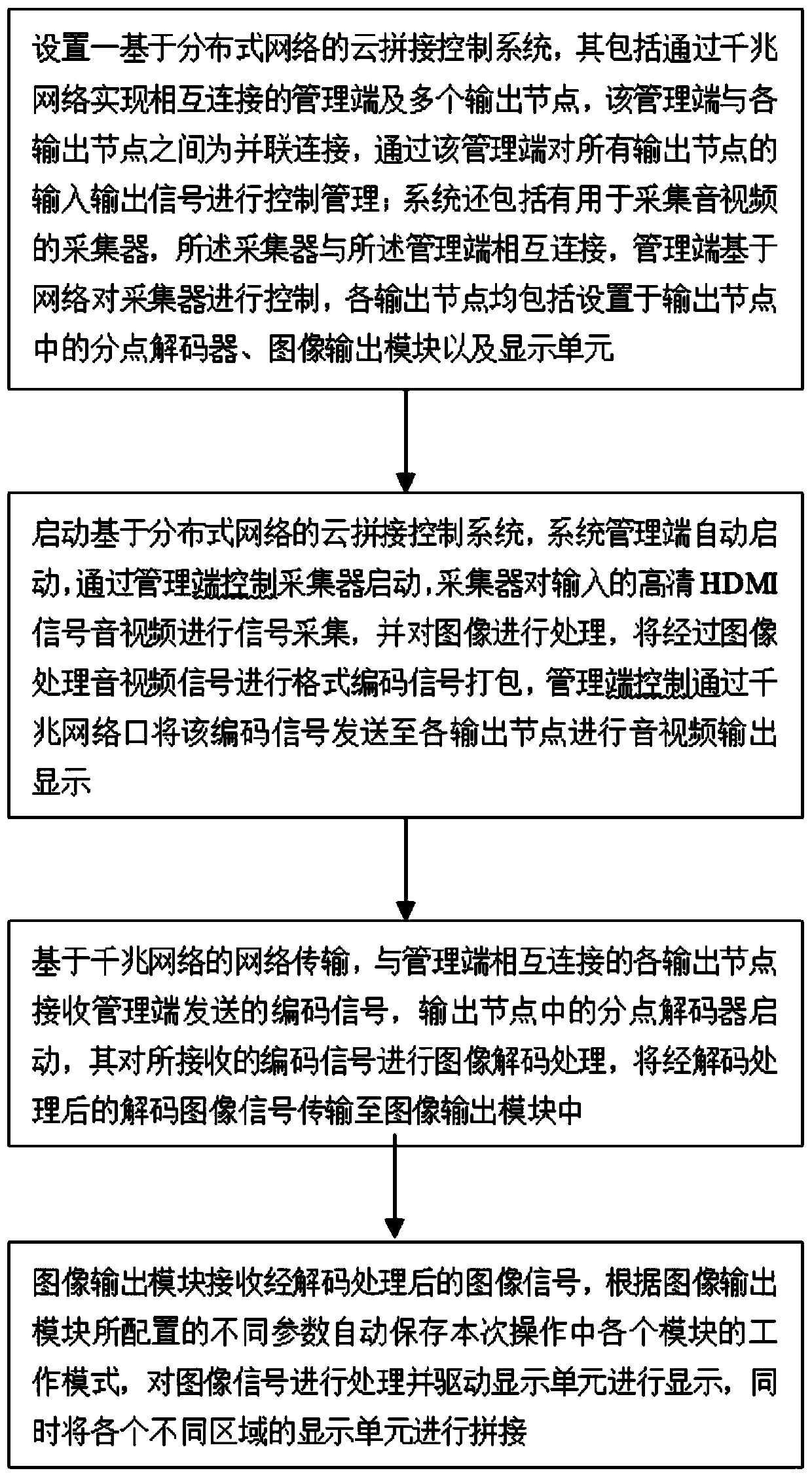
[0025] Referring to the accompanying drawings, the distributed network-based cloud splicing control method provided by the present invention includes the following steps:

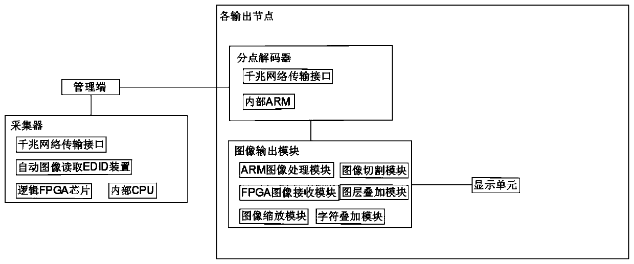
[0026] (1) Set up a cloud splicing control system based on a distributed network, which includes a management terminal and a plurality of output nodes connected to each other through a Gigabit network. The management terminal and each output node are connected in parallel. The input and out...


PUM


Abstract

The invention discloses a cloud splicing control method based on a distributed network, and the method comprises the following steps: (1) setting a cloud splicing control system based on the distributed network, wherein the cloud splicing control system comprises a management end and output nodes, the management end is in parallel connection with each output node, and each output node comprises adivision decoder, an image output module and a display unit; (2) starting the system, performing signal acquisition and processing on high-definition HDMI signal audios and videos by a collector, performing format encoding signal packaging on the audio and video signals, and sending the audio and video signals to each output node through a gigabit network port; (3) enabling each output node to receive the coded signal, starting a division decoder to decode the image, and transmitting the decoded image to an image output module; and (4) enabling the image output module to receive the image signals, processing the image signals and splicing the display units in all the areas. The invention further discloses a cloud splicing control system based on the distributed network for implementing themethod.

Description

technical field [0001] The invention relates to the technical field of image communication, in particular to a distributed network-based cloud mosaic control method and system. Background technique [0002] The video splicing wall is a large curtain wall made of multiple liquid crystal display units spliced ​​together as a display application. The traditional splicing mode is implemented based on the bus. It is not possible to transmit signals through cascading, and it is necessary to use a large-scale FPGA array for complex algorithm processing. The cost is extremely high, and the maximum is limited to 160 channels of signal output to the display unit, and there are problems that multiple scattered areas cannot be uniformly controlled at the same time. Cannot meet application requirements in large applications. [0003] In the prior art, the Chinese invention patent with the patent number 201610823175.1 discloses a video transmission and processing method based on a high-s...

Claims


Application Information

Patent Timeline
IPC IPC(8): H04N5/262H04N5/238H04N5/265
CPCH04N5/262H04N5/2628H04N5/265H04N23/75
Inventor 周远伦黄永兴
Owner 东莞市九鼎实业有限公司
Why Eureka
Try Eureka