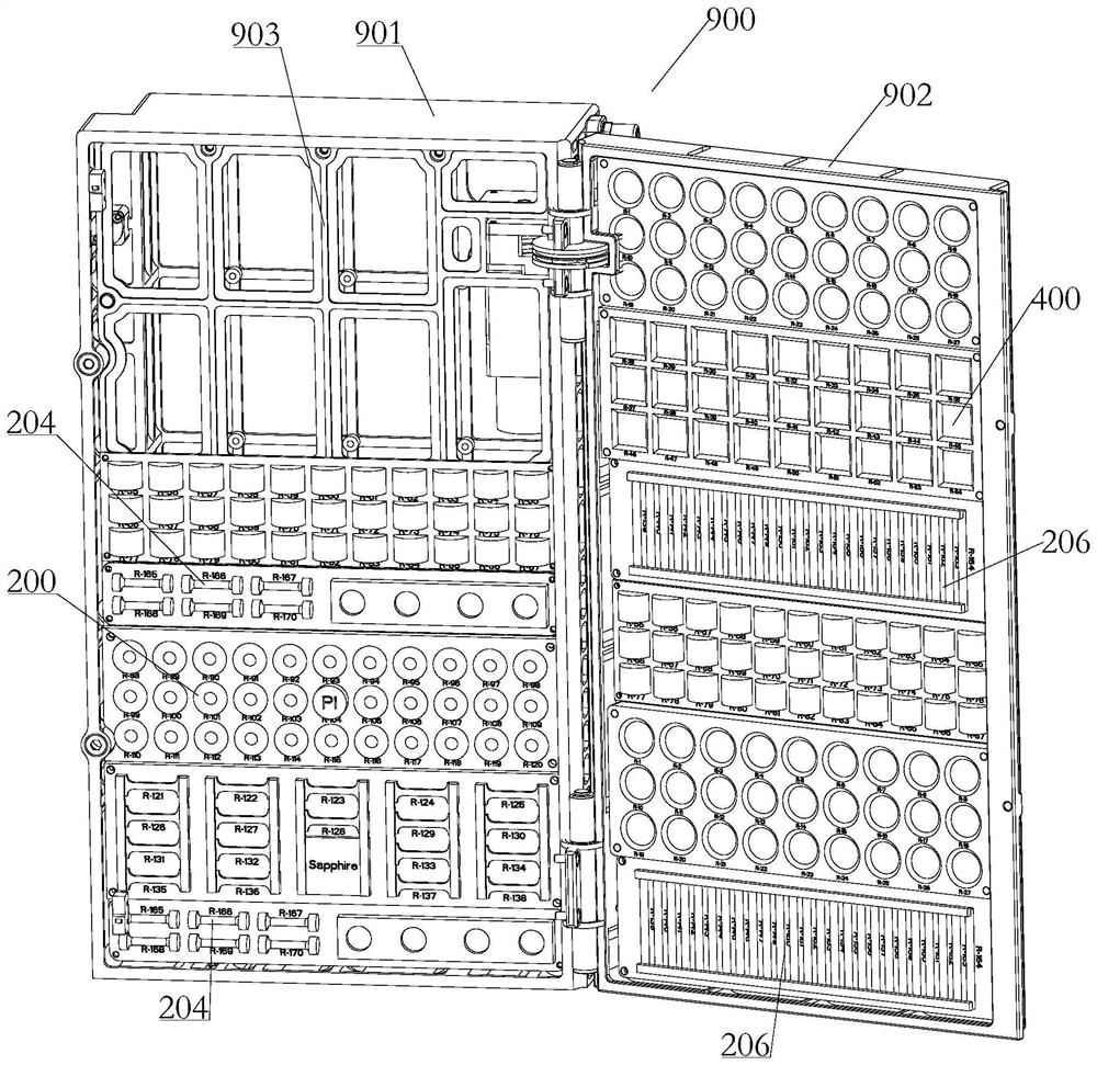
A modular test chamber for space material experiment samples
A test chamber and modular technology, applied in the field of aerospace material exposure experiments, can solve problems such as affecting the smooth progress of exposure experiments of other materials
- Summary
- Abstract
- Description
- Claims
- Application Information
AI Technical Summary
Problems solved by technology
Method used
Image
Examples
Embodiment 1
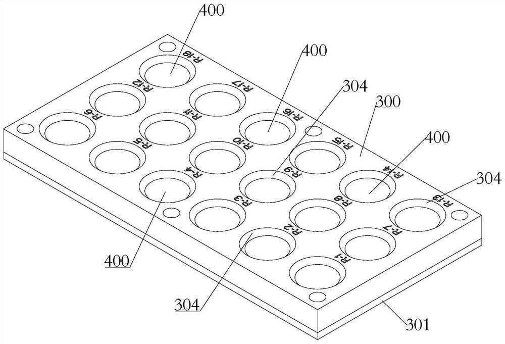
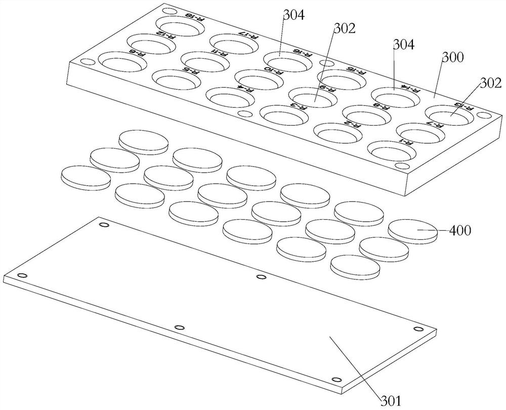
[0156] Such as Figure 2-Figure 4 As shown, this embodiment mainly relates to a general material module, the sample material is a general material, the installation support structure includes an upper cover 300 and a lower cover 301, and the upper cover 300 is provided with a number of exposure holes 302, the On the inner ring side of the upper end of the exposure hole 302, there is a circle of crimping edge 303, and the upper end of the crimping edge 303 is provided with a circle of chamfering 304 near the position of the exposing hole 302, and the specific chamfering angle is 45°; the lower cover plate 301 is detachable Installed on the lower end of the upper cover 300 , an installation space for installing materials is formed between the lower cover 301 and the pressing edge 303 .
[0157] Such as Figure 2-Figure 4 As shown, the general material of this embodiment is adapted to be installed in the installation space. The sample module of this embodiment can be used for e...
Embodiment 2
[0159] Such as Figure 5-Figure 8 As shown, the present embodiment mainly involves the functional material module, the sample material is a functional material, the installation support structure includes an upper cover 300 and a lower cover 301, and the upper cover 300 is provided with a number of exposure holes 302, so The upper end of the exposed hole 302 is provided with a circle of bevels 303 on the inner ring side, and the upper end of the bezels 303 is provided with a circle of chamfers 304 near the position of the exposed holes 302, and the specific design of the chamfers is 45°; the lower cover plate 301 can be It is disassembled and installed at the lower end of the upper cover plate 300 , and an installation space for installing materials is formed between the lower cover plate 301 and the pressing edge 303 .
[0160] Such as Figure 5-Figure 8As shown, the installation support structure of this embodiment also includes an O-ring 305, an isolation ring 306 and a su...
Embodiment 3
[0165] Such as Figure 9-Figure 11 As shown, the present embodiment mainly involves polymer material modules, and the installation support structure includes an upper cover plate 300 and a lower cover plate 301, and several exposure holes 302 are opened on the upper cover plate 300, and the upper ends of the exposure holes 302 are A circle of bevel 303 is provided on the inner ring side, and a circle of chamfer 304 is provided at the upper end of the bezel 303 close to the exposure hole 302, and the chamfer is specifically designed to be 45°; the lower cover 301 is detachably mounted on the At the lower end of the upper cover plate 300 , an installation space for installing materials is formed between the lower cover plate 301 and the pressing edge 303 .
[0166] Such as Figure 9-Figure 11 As shown, the installation support structure of this embodiment also includes a spacer plate 308 and an elastic support plate 309, the elastic support plate 309 is located above the lower ...
PUM
 Abstract
Description
Claims
Application Information
 - R&D
- Intellectual Property
- Life Sciences
- Materials
- Tech Scout
- Unparalleled Data Quality
- Higher Quality Content
- 60% Fewer Hallucinations
Browse by: Latest US Patents, China's latest patents, Technical Efficacy Thesaurus, Application Domain, Technology Topic, Popular Technical Reports.
© 2025 PatSnap. All rights reserved.Legal|Privacy policy|Modern Slavery Act Transparency Statement|Sitemap|About US| Contact US: help@patsnap.com


