Eureka AIR delivers breakthrough ideas for toughest innovation challenges, trusted by R&D personnel around the world.

Chemical laboratory drainage purifying equipment

A chemical laboratory and purification equipment technology, which is applied in the field of chemical laboratory drainage purification equipment, can solve the problems of bulky purification equipment, low purification efficiency, and large floor space, and achieve improved treatment effects, improved purification effects, and structural design. reasonable effect

Inactive Publication Date: 2020-04-14
国家海洋局北海海洋环境监测中心站
View PDF8 Cites 3 Cited by
  • Summary
  • Abstract
  • Description
  • Claims
  • Application Information

AI Technical Summary

Problems solved by technology

[0002] Wastewater treatment is to use physical, chemical and biological methods to treat wastewater, purify wastewater, reduce pollution, and achieve wastewater recycling and reuse, making full use of water resources. Laboratories, especially chemical laboratories, will produce a large amount of sewage. If Discharging directly without any treatment will cause huge damage. Wastewater treatment devices will be used when treating wastewater in chemical laboratories, but the existing laboratory wastewater treatment devices are generally pipelined treatment pools and other different The purification structure is easy to move, which makes the purification device bulky and occupies a large area. The chemical experiment wastewater also contains a large amount of toxic and refractory substances. It is difficult to achieve the purpose of effective purification of harmful substances only by acid-base neutralization. The purification efficiency is low and the purification effect is poor, and it is inevitable that there will be gas escape during the wastewater purification process, and the direct discharge will pollute the environment. Therefore, we propose a chemical laboratory drainage purification equipment

Method used


Image

  • Chemical laboratory drainage purifying equipment
  • Chemical laboratory drainage purifying equipment

Examples


Embodiment Construction

[0017] The following will clearly and completely describe the technical solutions in the embodiments of the present invention with reference to the accompanying drawings in the embodiments of the present invention. Obviously, the described embodiments are only some, not all, embodiments of the present invention. Based on the embodiments of the present invention, all other embodiments obtained by persons of ordinary skill in the art without making creative efforts belong to the protection scope of the present invention.

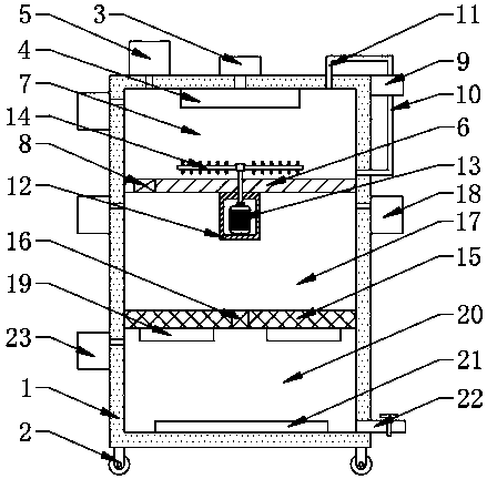
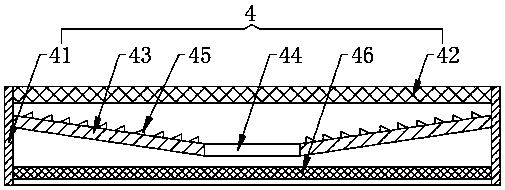
[0018] see figure 1 , the present invention provides a technical solution: a chemical laboratory drainage purification equipment, including a purification box 1, the four corners of the bottom of the purification box 1 are fixedly equipped with rollers 2, and the top center of the purification box 1 is fixedly equipped with a water supply pump 3 , the top of the inner cavity of the purification box 1 is fixedly provided with a filter 4 communicating with the f...


PUM


Abstract

The invention discloses chemical laboratorydrainage and purifying equipment, and belongs to the technical field of drainage and purifying equipment for chemical laboratories. A filter communicated with a water feeding pump is fixedly arranged at the top of an inner cavity of a purifying box; a first electromagnetic valve is fixedly assembled on the left side of a first partition plate; a second partition plate fixed on the inner wall of the purifying box is arranged below the first partition plate; a second electromagnetic valve is fixedly assembled on the second partition plate; a settling chamber is arranged between the second partition plate and the first partition plate; a precipitation medicine box matched with the settling chamber is fixedly arranged on the right side wall of the purifying box; ultrasonic generators are fixedly arranged on the left side and the right side of the bottom of the second partition plate; a photocatalysis plate is fixedly arranged at the bottom of theinner cavity of the purifying box, and a drainage pipe is fixedly assembled at the bottom of the right side wall of the purifying box, so that the catalytic oxidation treatment effect on wastewater isbetter, the chemical laboratory drainage and purifying equipment is economical and practical, the operation cost is low, and meanwhile, the treated water is relatively pure and relatively high in environmental protection property.

Description

technical field [0001] The invention relates to the technical field of chemical laboratory drainage purification equipment, in particular to a chemical laboratory drainage purification equipment. Background technique [0002] Wastewater treatment is to use physical, chemical and biological methods to treat wastewater, purify wastewater, reduce pollution, and achieve wastewater recycling and reuse, making full use of water resources. Laboratories, especially chemical laboratories, will produce a large amount of sewage. If Discharging directly without any treatment will cause huge damage. Wastewater treatment devices will be used when treating wastewater in chemical laboratories, but the existing laboratory wastewater treatment devices are generally pipelined treatment pools and other different The purification structure is easy to move, which makes the purification device bulky and occupies a large area. The chemical experiment wastewater also contains a large amount of toxic...

Claims


Application Information

Patent Timeline
Patent Type & Authority Applications(China)
IPC IPC(8): C02F9/08C02F101/30
CPCC02F1/001C02F1/30C02F1/36C02F1/52C02F1/66C02F1/725C02F1/78C02F9/00C02F2001/007C02F2101/30
Inventor 张春华李少朗
Owner 国家海洋局北海海洋环境监测中心站
Why Eureka
Eureka Blog
Learn More