
Pile foundation reinforcement cage installation centering device and structure and installation method of pile foundation reinforcement cage

A pile foundation reinforcement cage and centering device technology, applied in foundation structure engineering, foundation structure test, sheet pile wall, etc., can solve quality problems that cannot be effectively solved, reinforcement cage positioning and deviation correction, lower pier, abutment Construction impact and other issues, to achieve the effect of simple structure, easy storage and operation, and solve center deviation

Pending Publication Date: 2020-04-14
ROAD & BRIDGE INT +1
View PDF0 Cites 2 Cited by
  • Summary
  • Abstract
  • Description
  • Claims
  • Application Information

AI Technical Summary

Problems solved by technology

[0002] Pile foundation is the most common form of foundation in expressway construction; during the construction process of pile foundation underwater pouring method, since the water level in the hole is high after the pile foundation is formed, when the pile foundation reinforcement cage is lowered for installation, after lowering It is usually lower than the water level in the hole; therefore, the on-site measurement and technicians cannot locate and correct the center position of the upper part of the reinforcement cage well. The quality problem of this center deviation cannot be effectively solved. At present, visual or The lower installation process is guaranteed, and there is no inspection and judgment; but if the center of the steel cage is out of position beyond the technical requirements, it will affect the subsequent construction of the lower pier and abutment, and even have to rework and dig the pile foundation

Method used


Image

  • Pile foundation reinforcement cage installation centering device and structure and installation method of pile foundation reinforcement cage
  • Pile foundation reinforcement cage installation centering device and structure and installation method of pile foundation reinforcement cage
  • Pile foundation reinforcement cage installation centering device and structure and installation method of pile foundation reinforcement cage

Examples


Embodiment Construction

[0032] Embodiments of the present invention are described below through specific examples, and those skilled in the art can easily understand other advantages and effects of the present invention from the content disclosed in this specification. The present invention can also be implemented or applied through other different specific implementation modes, and various modifications or changes can be made to the details in this specification based on different viewpoints and applications without departing from the spirit of the present invention. It should be noted that the diagrams provided in the following embodiments are only schematically illustrating the basic concept of the present invention, and the following embodiments and the features in the embodiments can be combined with each other in the case of no conflict.

[0033] Wherein, the accompanying drawings are for illustrative purposes only, and represent only schematic diagrams, rather than physical drawings, and should...


PUM


Abstract

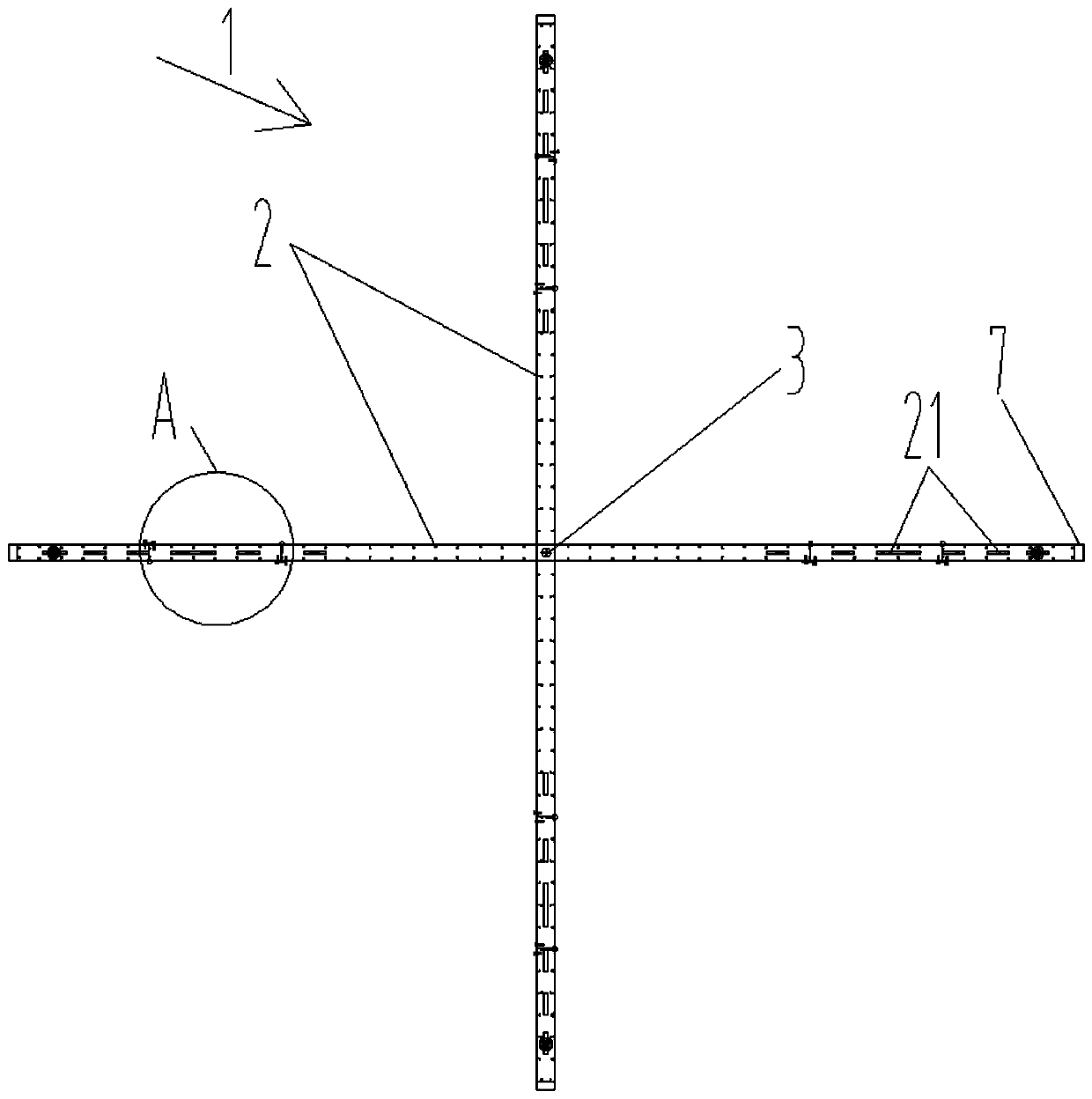
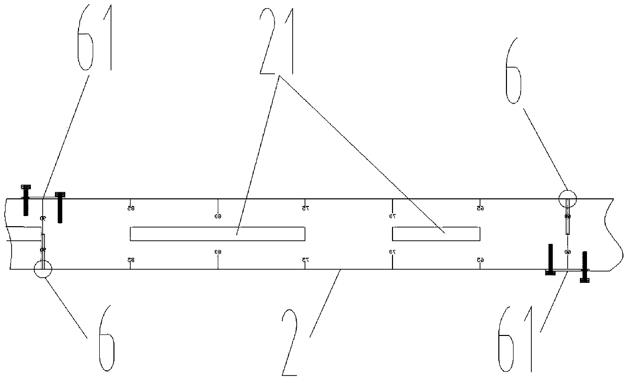
The invention relates to a pile foundation reinforcement cage installation centering device and structure and an installation method of a pile foundation reinforcement cage, and belongs to the technical field of drilling of soil layers or rocks in a building. The centering device comprises straight-strip-shaped measuring scales, two measuring scales are horizontally arranged in an up-and-down overlapping manner, the middle parts of the two measuring scales are rotatably connected through a vertical rotating shaft so that the two measuring scales can rotate along the vertical rotating shaft toform a cross-shaped cross shape, and the vertical rotating shaft is located in the central position of the length direction of the two measuring scales; the two ends of the measuring scales are slidably connected with positioning buttons respectively, the positioning buttons can slide in the length direction of the measuring scales and are fixed so as to conveniently adjust positions, and the vertically downward positioning buttons protrude out of the lower surfaces of the measuring scales, the two positioning buttons on the measuring scales are symmetrically arranged in the center of the vertical rotating shaft. When in use, the centering device is connected to sleeves of the four vertical steel bars at the upper end of the reinforcement cage in a horizontal manner, the center position ofthe upper end of the reinforcement cage is obtained through the position of the vertical rotating shaft of the centering device, and then the deviation of the center of the upper end of the reinforcement cage and the center of a pile hole port is conveniently adjusted to meet the design requirement.

Description

technical field [0001] The invention belongs to the technical field of drilling into soil layers or rocks in buildings, and in particular relates to a centering device for installing a pile foundation reinforcement cage, a structure and an installation method. Background technique [0002] Pile foundation is the most common form of foundation in expressway construction; during the construction process of pile foundation underwater pouring method, since the water level in the hole is high after the pile foundation is formed, when the pile foundation reinforcement cage is lowered for installation, after lowering It is usually lower than the water level in the hole; therefore, the on-site measurement and technicians cannot locate and correct the center position of the upper part of the reinforcement cage well. The quality problem of this center deviation cannot be effectively solved. At present, visual or The lower installation process is guaranteed, and there is no inspection ...

Claims


Application Information

Patent Timeline
Patent Type & Authority Applications(China)
IPC IPC(8): E02D33/00E02D5/34
CPCE02D33/00E02D5/34E02D2300/0034
Inventor 李芃雨段志龙马晓涛
Owner ROAD & BRIDGE INT
Learn More