Cavity structure using wave-absorbing material
A wave-absorbing material and cavity technology, which is applied in the field of aircraft stealth, can solve the problems of high cost of high-performance wave-absorbing materials, and achieve the effects of improving wave-absorbing performance, avoiding use, and effectively controlling
- Summary
- Abstract
- Description
- Claims
- Application Information
AI Technical Summary
Problems solved by technology
Method used
Image
Examples
Embodiment 1
[0048] The first step: cavity structure model selection and model processing
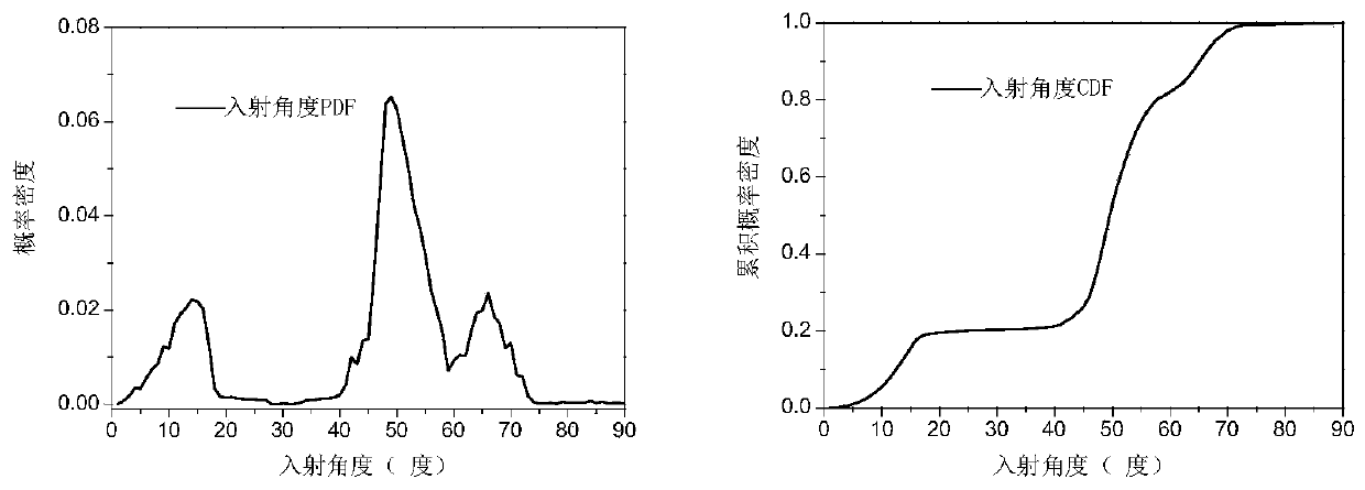
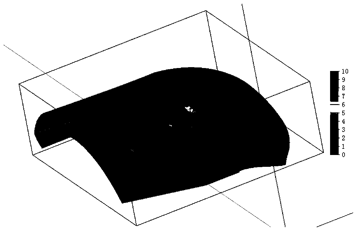
[0049] According to the model or project requirements, select a specific aircraft inlet, mesh the inner surface, and use it to calculate the reflection angle: firstly, extract the equal-section data points of the inlet, starting from the inlet of the inlet, and then Take equidistant cross-section points of the inlet duct at intervals of 100 mm to obtain a certain number of cross-sections, select 100 data points for each cross-section, and then use the selected data points to form triangular surface elements to establish a calculation model. Process the inlet model, extract the inner surface of the model and design a surface field recorder for surface field strength simulation and analysis.
[0050] Step 2: Analysis and Statistics of Electromagnetic Wave Reflection Angle
[0051] The calculation parameters for the analysis and statistics of electromagnetic wave reflection angle include incident azim...
Embodiment 2
[0061] Step 1: Aircraft cavity structure model selection and model processing
[0062] Select a typical square air inlet, and divide the inner surface into a grid for calculating the reflection angle: firstly, the data points of the equal section of the air inlet are extracted, starting from the inlet of the air inlet, the air inlet is measured at intervals of 10mm Take equidistant cross-section points to obtain a certain number of cross-sections, select 20 data points for each cross-section, and then use the selected data points to form triangular surface elements to establish a calculation model. Process the inlet model, extract the inner surface of the model and design a surface field recorder for surface field strength simulation and analysis.
[0063] Step 2: Analysis and Statistics of Electromagnetic Wave Reflection Angle
[0064] The calculation parameters of electromagnetic wave reflection angle analysis and statistics include incident azimuth angle 0°~80°, azimuth an...
Embodiment 3
[0074] The first step: cavity structure model selection and model processing
[0075] According to the model or project requirements, select a specific aircraft exhaust pipe, mesh the inner surface, and use it to calculate the reflection angle: firstly, the exhaust pipe is extracted with equal cross-section data points, starting from the outlet of the exhaust system, and then Take equidistant cross-section points of the exhaust pipe at intervals of 100 mm to obtain a certain number of cross-sections, select 100 data points for each cross-section, and then use the selected data points to form triangular surface elements to establish a calculation model. Process the inlet model, extract the inner surface of the model and design a surface field recorder for surface field strength simulation and analysis.
[0076] Step 2: Analysis and Statistics of Electromagnetic Wave Reflection Angle
[0077] The calculation parameters for the analysis and statistics of electromagnetic wave ref...
PUM
 Abstract
Description
Claims
Application Information
 - R&D
- Intellectual Property
- Life Sciences
- Materials
- Tech Scout
- Unparalleled Data Quality
- Higher Quality Content
- 60% Fewer Hallucinations
Browse by: Latest US Patents, China's latest patents, Technical Efficacy Thesaurus, Application Domain, Technology Topic, Popular Technical Reports.
© 2025 PatSnap. All rights reserved.Legal|Privacy policy|Modern Slavery Act Transparency Statement|Sitemap|About US| Contact US: help@patsnap.com


