Crop airing device

A drying device and a technology for crops, which are applied to drying solid materials, drying gas layout, dryers for stationary materials, etc. Uneven drying effect

Active Publication Date: 2020-04-14
JILIN TEACHERS INST OF ENG & TECH
View PDF7 Cites 6 Cited by
  • Summary
  • Abstract
  • Description
  • Claims
  • Application Information

AI Technical Summary

Problems solved by technology

The disadvantages of this drying structure are: on the one hand, after the drying is completed, the crops need to be bagged and stored. Currently, tools are used to collect them, which is labor-intensive and requires two people to operate. On the other hand, it is directly spread on the road. The road surface is easy to regain moisture, and the crops must be overturned to ensure sufficient drying, so the labor load is large, so we propose a crop drying device to solve the existing problems

Method used


Image

  • Crop airing device
  • Crop airing device
  • Crop airing device

Examples


Embodiment 1

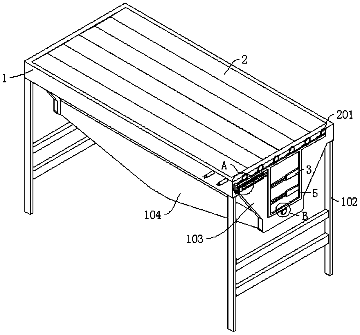
[0030] refer to Figure 1-9 , a crop drying device, including a bracket 1, and also includes a connecting frame 5 slidably connected to the side wall of the bracket 1, the side wall of the bracket 1 is connected with a driving part for pushing the connecting frame 5 to slide on the bracket 1;

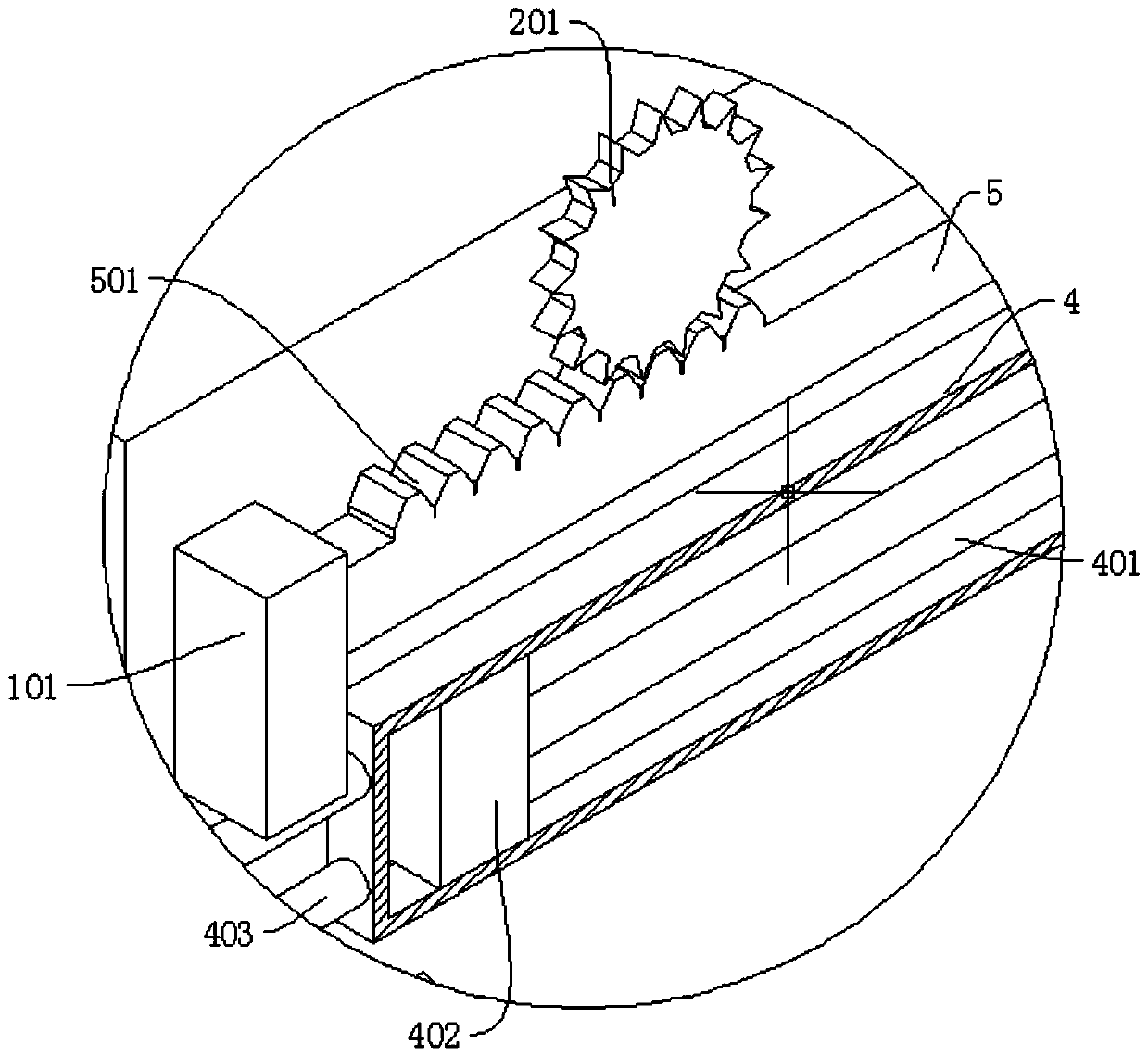
[0031] The drying device also includes a plurality of drying boards 2 rotatably connected to the bracket 1. The side wall of the bracket 1 is connected with a plurality of first gears 201, and the plurality of first gears 201 are fixedly connected with the drying board 2 to drive the drying board 2 to rotate. The upper end of the connecting frame 5 is connected with a first gear tooth 501, and the first gear tooth 501 meshes with the first gear 201;

[0032] The bottom of the bracket 1 is fixedly connected with a first collecting box 103, the bottom of the first collecting box 103 is fixedly connected with a second collecting box 104, the bottom of the first collecting box 103 is connec...

Embodiment 2

[0035] refer to Figure 2-6 , which is basically the same as that of Embodiment 1, furthermore, the bracket 1 is located on the side wall of the connecting frame 5 and is connected with a first sealed box 4, and the first sealed box 4 is slidably connected with a first air-tight block 402, the first The air seal block 402 is fixedly connected with a push rod 401, the other end of the push rod 401 is fixedly connected with the connecting frame 5, the side wall of the support 1 is connected with a second sealing box 404, and the second sealing box 404 is slidingly connected with a second gas The sealing block 405, the second air sealing block 405 is fixedly connected with the insertion rod 406, and the drying plate 2 is dug with a socket 202, and the end of the insertion rod 406 away from the second air sealing block 405 passes through the side wall of the bracket 1 and is inserted into the socket 202 , the first sealed box body 4 and the second sealed box body 404 are sealed an...

Embodiment 3

[0038] refer to Figure 7 , is basically the same as in Embodiment 1, furthermore, the bottom of the first collecting box 103 is connected with an arc-shaped baffle 1031, and the side wall of the sealing plate 602 is arc-shaped, so that the sealing plate 602 and the first collecting The box 103 fits closely to further prevent material leakage.

[0039] The cross section of the first collecting box 103 is triangular and the bottom is provided with an opening communicating with the second collecting box 104 .

[0040] The bottom of the second collecting box 104 is provided with a discharge port, which is convenient for the grains to be concentrated, so that the discharge port is discharged.

[0041] Cylinder 3 is used as the drive unit.


PUM


Abstract

The invention discloses a crop airing device, and belongs to the field of airing devices. The crop airing device comprises a support and further comprises a connecting frame connected to the side wallof the support in a sliding mode, the airing device further comprises a plurality of airing plates connected to the support in a rotating mode, and a plurality of first gears are connected to the side wall of the support. A first collecting box is fixedly connected to the bottom of the support, a second collecting box is fixedly connected to the bottom of the first collecting box, a rotating shaft is rotatably connected to the bottom of the first collecting box, a sealing plate is fixedly connected to the rotating shaft, a second gear is connected to the side wall of the support, and second gear teeth are connected to the bottom of the connecting frame and engaged with the second gear teeth. According to the invention, the airing plane is formed by overturning the plurality of airing plates; according to the crop airing device, the airing plate is turned over to collect crops in a centralized mode after airing is completed, so that the working efficiency is improved, meanwhile, a heating assembly is additionally arranged in the first material collecting box, hot air exists at the bottom of the airing plate, and uneven airing caused by grain moisture regaining is prevented.

Description

technical field [0001] The invention relates to the technical field of drying devices, in particular to a drying device for crops. Background technique [0002] For granular crops such as rice, peanuts and corn, they need to be dried before they can be stored in the warehouse. At present, a drying platform is usually used for drying. The drying platform is evenly distributed. After drying, the drying objects are accumulated into piles with the help of corresponding tools, and then collected and put into storage. The disadvantages of this drying structure are: on the one hand, after the drying is completed, the crops need to be bagged and stored. Currently, tools are used to collect them, which is labor-intensive and requires two people to operate. On the other hand, it is directly spread on the road. The road surface is easy to regain moisture, and the crops must be overturned to ensure sufficient drying. Therefore, the labor load is large. For this reason, we propose a cro...

Claims


Application Information

Patent Timeline
Patent Type & Authority Applications(China)
IPC IPC(8): F26B9/10F26B21/00F26B25/00F26B25/04F26B25/18
CPCF26B9/10F26B21/001F26B25/008F26B25/04F26B25/18
Inventor 王鹏赵丽艳郑作涛王玉双张伟东
Owner JILIN TEACHERS INST OF ENG & TECH
Why Eureka
Try Eureka