Magnetic encoder and angle calculation method thereof

A magnetic encoder and magnetic disk technology, applied in the field of magnetic encoder and its angle calculation, can solve problems such as the inability to determine the initial angle, and achieve the effect of compact structure, reduction of mechanical structure, and optimization of encoder structure

Active Publication Date: 2020-04-14
ZHEJIANG LINIX MOTOR
View PDF11 Cites 4 Cited by
  • Summary
  • Abstract
  • Description
  • Claims
  • Application Information

AI Technical Summary

Problems solved by technology

[0008] The present invention is aimed at the problem that the existing magnetic encoder usually judges the rotation direction through the double-function phase transition, and cannot determine the initial angle when restarting, and designs a magnetic encoder. By changing the position of the Hall sensor, the actual voltage function can be changed. The characteristic point of the maximum amplitude value is used to judge the initial angle when the encoder starts

Method used


Image

  • Magnetic encoder and angle calculation method thereof
  • Magnetic encoder and angle calculation method thereof
  • Magnetic encoder and angle calculation method thereof

Examples


Embodiment 1

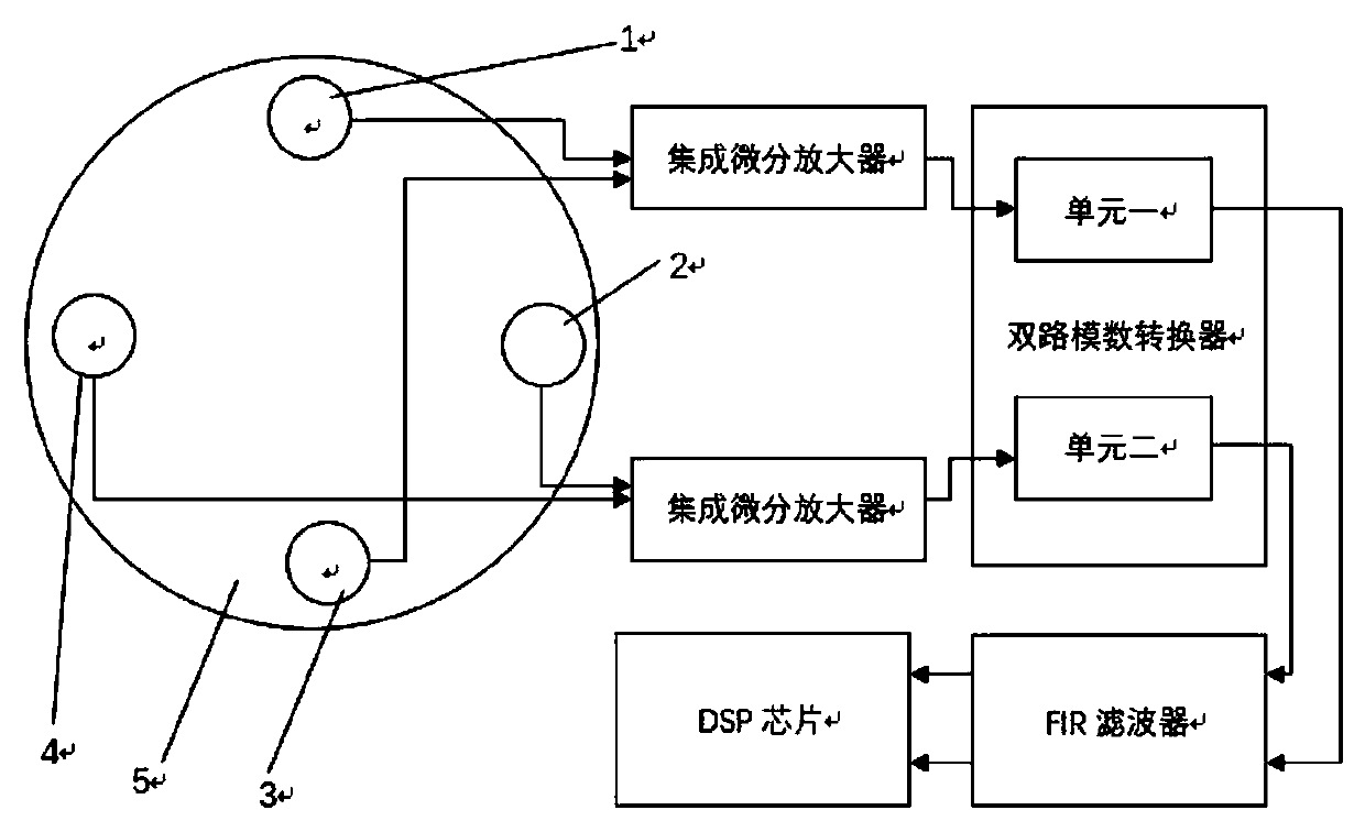
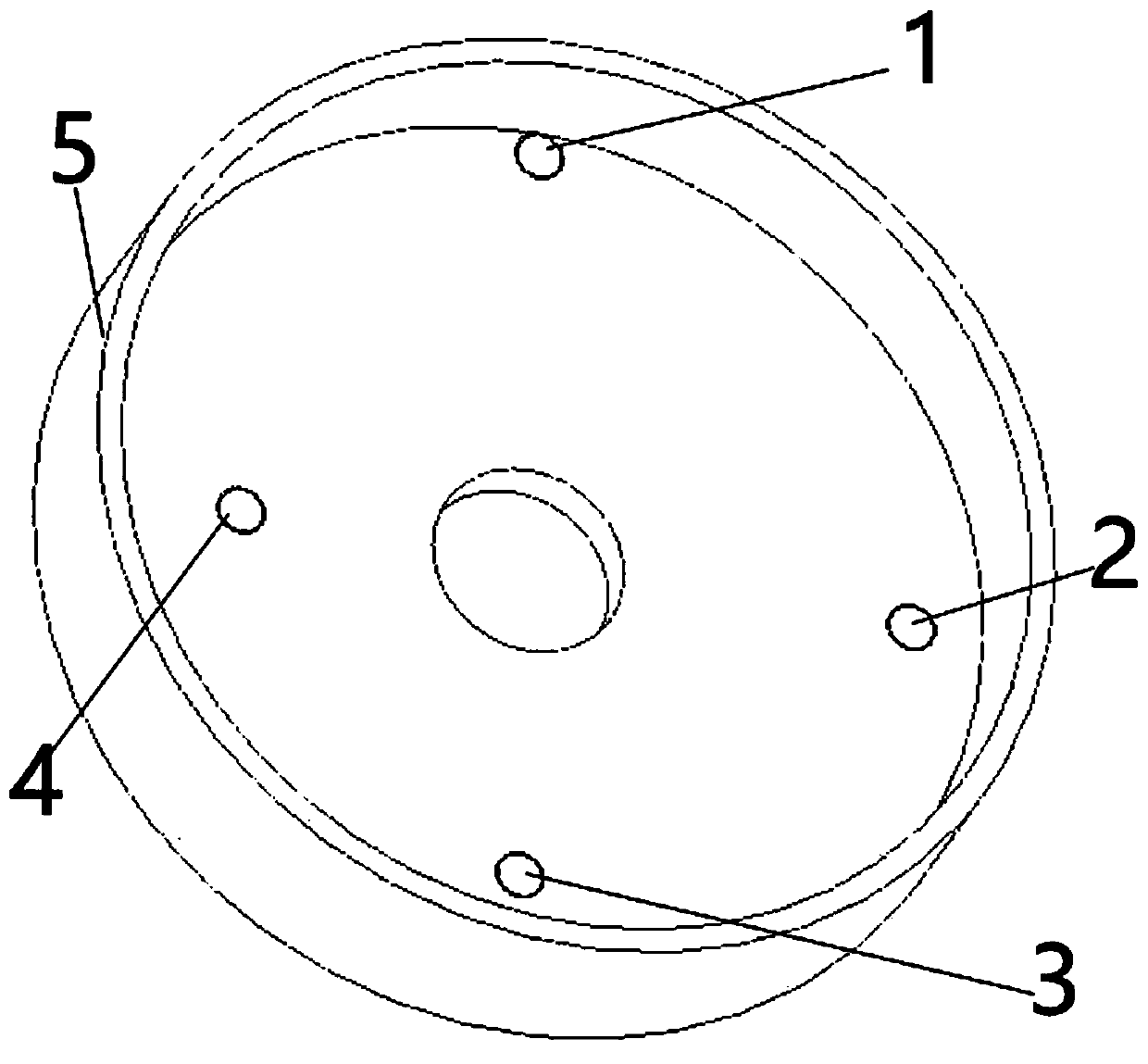
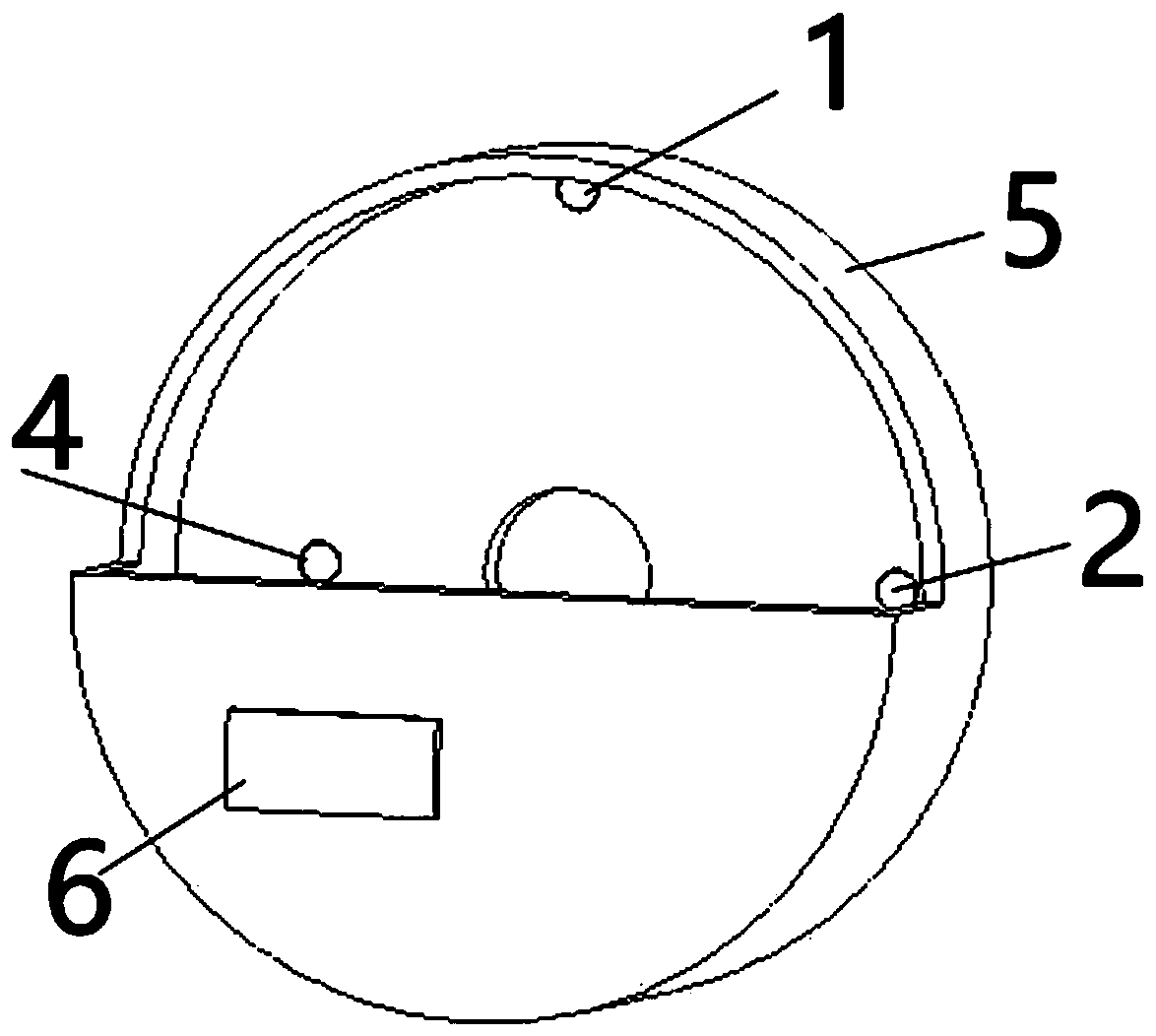
[0049] Such as figure 1 , figure 2 , image 3 with Figure 4 Shown, described a kind of magnetic encoder comprises:

[0050] The casing 5 is divided into upper and lower casings to form a cylindrical cavity in the middle;

[0051] The magnetic disk 7 is used to be arranged on the rotating shaft to read the rotation state of the rotating shaft, and is arranged in the casing 5 and is hinged with the casing 5;

[0052] Four Hall elements are arranged in a circle on the same side of the casing 5 and work together with the magnetic disk 7;

[0053] An integrated differential amplifier is used to calculate the continuously output voltage value of the Hall element into a continuous function, and at least two sets of input ends are electrically connected to the output end of the Hall element;

[0054] A dual-channel analog-to-digital converter is used to convert a continuous analog function into a digital signal, and the analog input terminal is electrically connected to the out...


PUM


Abstract

A magnetic encoder comprises a sleeve shell which is divided into an upper shell, a lower shell and a cylindrical cavity formed therebetween; a magnetic disk which is arranged on a rotating shaft to read the rotating state of the rotating shaft, arranged in the sleeve shell and hinged to the sleeve shell; four Hall elements which are circumferentially arranged in the same surface of the sleeve shell and are matched with the magnetic disk to work; an integrated differential amplifier which is used for calculating the continuously output voltage value of the Hall elements into a continuous function, and provided with at least two groups of input ends electrically connected with the output ends of the Hall elements; a double-channel analog-to-digital converter which is used for converting thecontinuous analog function into a digital signal, and provided with an analog input end electrically connected with the output end of the integrated differential amplifier; at least two FIR filters in which the input ends are electrically connected with the two output ends of the two-way analog-to-digital converter respectively; and a DSP integrated chip which is used for comparing the two digital functions to calculate an actual coding angle.

Description

technical field [0001] The invention relates to an encoder structure, in particular to a magnetic encoder and an angle calculation method thereof. Background technique [0002] An encoder is a device that compiles and converts signals (such as bit streams) or data into signal forms that can be used for communication, transmission, and storage. The encoder converts angular displacement or linear displacement into an electrical signal, the former is called a code disc, and the latter is called a yardstick. According to the readout method, the encoder can be divided into two types: contact type and non-contact type; according to the working principle, the encoder can be divided into two types: incremental type and absolute type. The incremental encoder converts the displacement into a periodic electrical signal, and then converts the electrical signal into a counting pulse, and uses the number of pulses to represent the magnitude of the displacement. Each position of the abso...

Claims


Application Information

Patent Timeline
IPC IPC(8): G01D5/14G01B7/30
CPCG01D5/142G01B7/30
Inventor 王帅
Owner ZHEJIANG LINIX MOTOR
Why Eureka
Try Eureka