Optical fiber testing system based on cloud computing
A technology of optical fiber testing and cloud computing, applied to radio wave measurement systems, transmission systems, digital transmission systems, etc., can solve problems such as limited coverage, high deployment costs, and heavy maintenance burdens, and reduce deployment difficulty and cost, expand The effect of testing scope and fast deployment cycle
Pending Publication Date: 2020-04-14
浙江光维通信技术有限公司
View PDF0 Cites 2 Cited by
- Summary
- Abstract
- Description
- Claims
- Application Information
AI Technical Summary
Problems solved by technology
However, the OTDR equipment of the current remote automatic OTDR test system is arranged in the computer room and is divided into acquisition modules, optical switch modules, communication modules, etc., the deployment cost is high, and it is impossible to form a flexible optical fiber detection network, and the coverage is limited.
Moreover, since the system operates independently, network equipment, storage systems, dedicated servers, OS, etc. all need to be established and deployed by themselves, the cycle from planning, project approval, procurement, construction to delivery is relatively long, the construction cost is high, and the maintenance burden after completion is heavy. The system is not easy upgrade
Method used
View moreImage
Smart ImageViewing Examples
Examples
Embodiment 1
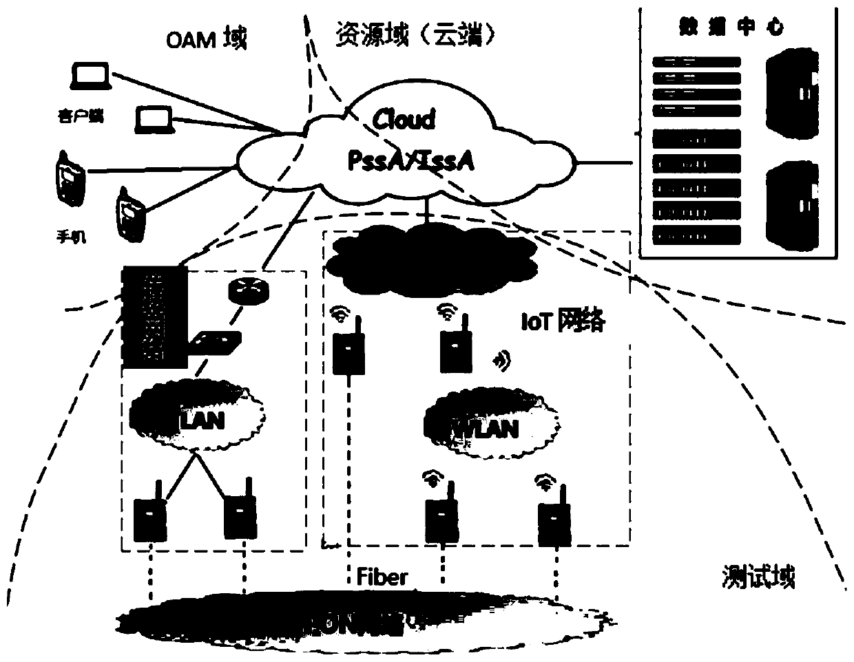
[0047] Such as figure 1 As shown, the present embodiment is a cloud computing-based optical fiber testing system, including:
Login to View More PUM
 Abstract
The invention relates to an optical fiber testing system based on cloud computing, and the system comprises a test subsystem which is used for collecting optical fiber testing data; a resource subsystem which is connected with the test subsystem and is used for carrying out parameter calculation on the optical fiber test data. The test subsystem comprises a plurality of optical fiber test devices,wherein each optical fiber test device is connected with a resource subsystem through a network; and the resource subsystem operates on a cloud computing platform. Compared with the prior art, the system has the advantages of being short in deployment period, high in reliability, scalability, dynamics, virtualization and expandability, low in price, flexible and good in stability.
Description
technical field [0001] The invention relates to the field of optical fiber testing systems, in particular to a cloud computing-based optical fiber testing system. Background technique [0002] The traditional way of using OTDR (Optical Time Domain Reflectometer) is manual, decentralized, and non-real-time. It has the characteristics of low work efficiency, excessive dependence on user experience, and requires a large number of maintenance personnel. With the long-distance transmission of optical cables and the rapid expansion of the scale of the local network, the maintenance force becomes more and more insufficient. With the maturity of optical fiber network and the advancement of technology, in order to ensure the availability of communication, the demand of operators is getting higher and higher, and it is necessary to adopt remote automatic maintenance methods, especially for some important optical fiber lines. The optical fiber test system is required to have 1) real-...
Claims
Login to View More Application Information
Patent Timeline
 Patent Type & Authority Applications(China)
IPC IPC(8): H04B10/071H04L12/24H04L29/06G01S19/42
CPCG01S19/42H04B10/071H04L41/0213H04L41/0631H04L69/18
Inventor 洪波
Owner 浙江光维通信技术有限公司
Features
- R&D
- Intellectual Property
- Life Sciences
- Materials
- Tech Scout
- Unparalleled Data Quality
- Higher Quality Content
- 60% Fewer Hallucinations
Learn More Browse by: Latest US Patents, China's latest patents, Technical Efficacy Thesaurus, Application Domain, Technology Topic, Popular Technical Reports.
© 2025 PatSnap. All rights reserved.Legal|Privacy policy|Modern Slavery Act Transparency Statement|Sitemap|About US| Contact US: help@patsnap.com


