

Special injector for telescopic push rod type chain hemostatic device
A syringe and push rod technology, applied in the field of special syringes for telescopic push rod type chain type hemostatic devices, can solve the problems of inconvenient operation, incomplete hemostasis, poor hemostasis effect, etc. Effect
- Summary
- Abstract
- Description
- Claims
- Application Information
AI Technical Summary
Problems solved by technology
Method used
Image

Examples
Embodiment Construction
[0028] The present invention will be described in detail below in conjunction with the accompanying drawings and specific embodiments.
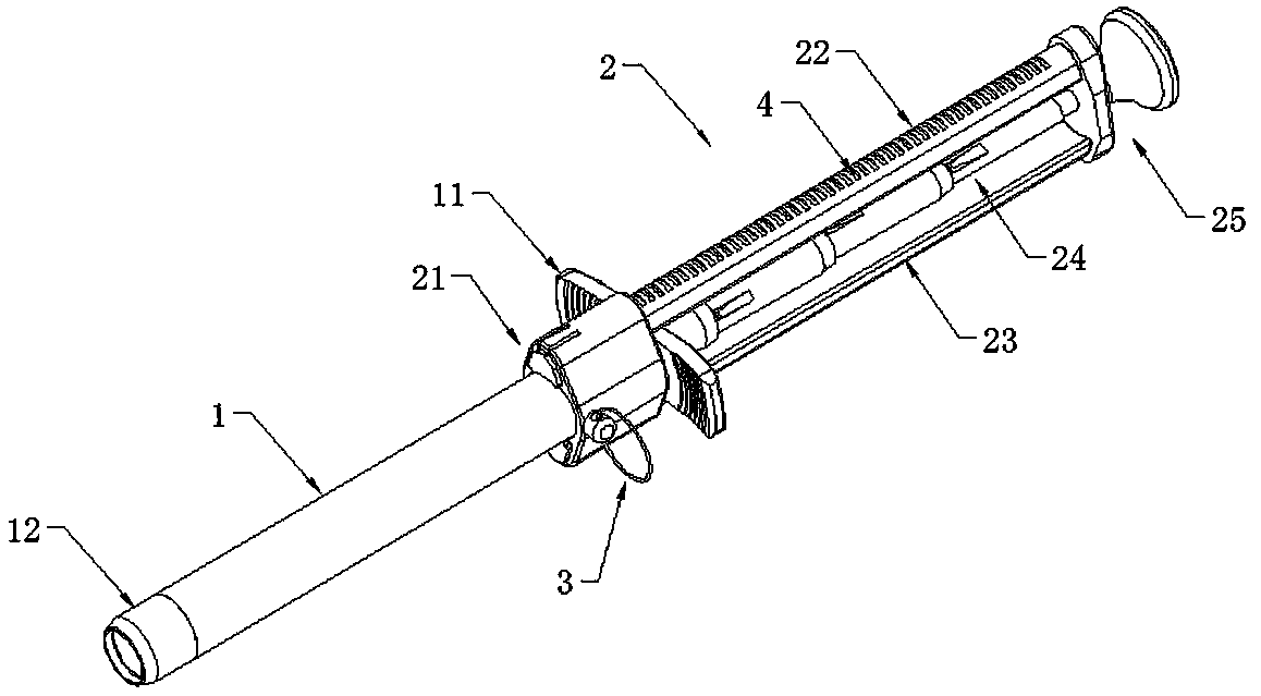
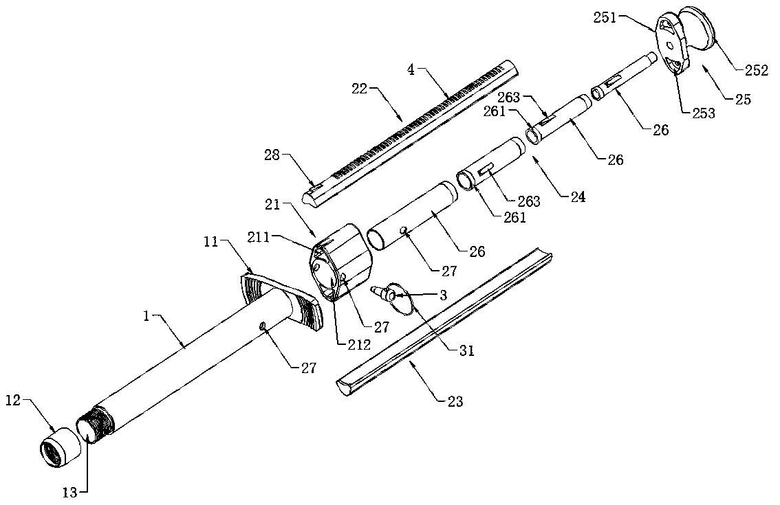
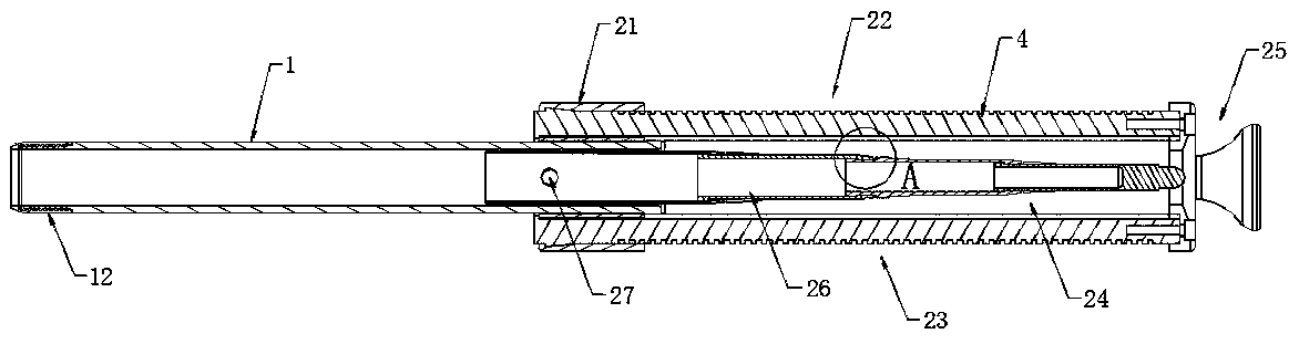
[0029] see Figure 1 to Figure 5 , a special syringe for telescopic push rod type chain hemostatic device, including a syringe 1 for storing the chain hemostatic device and a propulsion mechanism 2 for pushing the syringe 1 to move; the chain hemostatic device is made of an expandable A hemostatic chain formed by series connection of hemostatic materials, the adjacent hemostatic materials on the hemostatic chain can be extruded and shrunk and stored in the injection tube 1. When in use, the hemostatic chain is pushed into the wound for hemostasis; the tail of the injection tube 1 is fixed with a The handle 11 of the injection tube 1 is vertical and extends outward. The handle 11 is convenient for the operator to pull the injection tube 1; Cover piece 22 and lower cover piece 23, the telescopic push rod 24 that is arranged in the accommodatin...
PUM
 Abstract
Description
Claims
Application Information