Drilling auxiliary device for electric hand drill

An auxiliary device and hand electric drill technology, which is used in drilling/drilling equipment, portable drilling rigs, metal processing equipment, etc., can solve the problems of long drilling time, short drill pipe distance, slippage, etc. Effect

Pending Publication Date: 2020-04-17
李广超
View PDF12 Cites 0 Cited by
  • Summary
  • Abstract
  • Description
  • Claims
  • Application Information

AI Technical Summary

Problems solved by technology

[0002] When using a hand electric drill to drill a hole in a plate workpiece, since the driller is on one side of the workpiece, the driller needs to control the angle between the drill rod and the surface of the workpiece in real time to make the drill rod drill in the predetermined drilling direction. Continuously apply enough pressure in the drilling direction so that the drill pipe can drill into the workpiece, but when the material is hard and thick, it is easy to slip and deviate from the drilling direction. It is difficult for personnel to well control the magnitude and direction of the applied force, which makes drilling laborious. In the existing device, the device is installed on the drill pipe of the electric drill, and the structure fixed with the electric drill and the plate structure used to clamp the workpiece pass through single or multiple The rod is connected, the rod is close to the drill pipe,

Method used


Image

  • Drilling auxiliary device for electric hand drill
  • Drilling auxiliary device for electric hand drill
  • Drilling auxiliary device for electric hand drill

Examples


Embodiment Construction

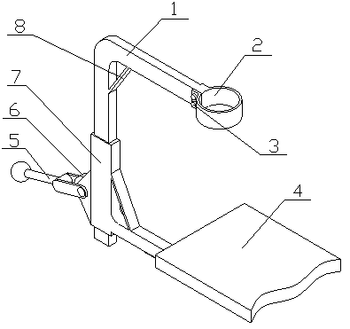
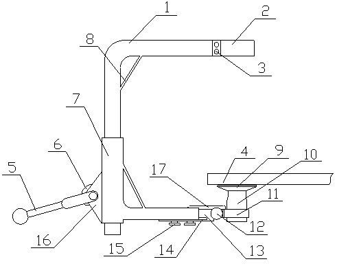
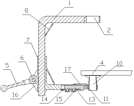
[0018] A hand electric drill drilling auxiliary device of the present invention is realized in the following way: a hand electric drill drilling auxiliary device of the present invention is composed of a main device and a supporting device, and the main device is composed of an L-shaped splint (1), a fixing ring (2), a fixing Bolt (3), rotating rod (5), gear (6), sliding sleeve (7), reinforcement plate (8), telescopic rod (13), positioning plate (14), fixing knob (15) and fixing seat (16 ), the L-shaped splint (1) is composed of a horizontal plate and a vertical plate fixedly connected, a reinforcement plate (8) is placed between the horizontal plate and the vertical plate, and teeth are placed on one side of the vertical plate The sliding sleeve (7) is an L-shaped sleeve composed of a vertical tube and a horizontal tube, a reinforcing rod is placed between the vertical tube and the horizontal tube, and the vertical tube sleeve of the sliding sleeve (7) is placed On the vertic...


PUM


Abstract

The invention discloses a drilling auxiliary device for an electric hand drill. The distance is adjusted through a telescopic rod, the drilling range is wide, the angle between a drilling machine anda workpiece can be adjusted, and time and labor are saved. The drilling auxiliary device for the electric hand drill is characterized in that an L-shaped clamping plate is formed by fixedly connectinga transverse plate and a vertical plate, a reinforcing plate is arranged between the transverse plate and the vertical plate, a rack is arranged on one side of the vertical plate, a sliding sleeve isan L-shaped sleeve composed of a vertical pipe and a transverse pipe, a reinforcing rod is arranged between the vertical pipe and the transverse pipe, the vertical pipe of the sliding sleeve is arranged on the vertical plate of the L-shaped clamping plate in a sleeving manner, the sliding sleeve can slide along the vertical plate, a fixing base is fixedly arranged on one side of the vertical pipeof the sliding sleeve, one end of a rotating rod is arranged on the fixing base through a connecting shaft, a gear is arranged on the connecting shaft in a sleeving manner, a receding groove is formed in one side of the vertical pipe of the sliding sleeve, the gear is engaged with the rack on one side of the vertical plate through the receding groove, and a notch is formed in the gear to form a plane.

Description

technical field [0001] The invention relates to a drilling auxiliary device for a hand electric drill, which relates to a device for assisting drilling with a hand electric drill, and belongs to the field of mechanical equipment. In particular, it relates to a time-saving and labor-saving auxiliary device which can adjust the distance through the telescopic rod, has a wide drilling range, and can adjust the angle between the drilling machine and the workpiece. Background technique [0002] When using a hand electric drill to drill a hole in a plate workpiece, since the driller is on one side of the workpiece, the driller needs to control the angle between the drill rod and the surface of the workpiece in real time to make the drill rod drill in the predetermined drilling direction. Continuously apply enough pressure in the drilling direction so that the drill pipe can drill into the workpiece, but when the material is hard and thick, it is easy to slip and deviate from the d...

Claims


Application Information

Patent Timeline
IPC IPC(8): B23B45/14B25H1/00
CPCB25H1/0021
Inventor 不公告发明人
Owner 李广超
Why Eureka
Try Eureka