Automatic edge finding and grinding device for specially shaped metal part

A technology for automatic edge finding and special-shaped parts, which is applied in grinding/polishing safety devices, metal processing equipment, and machine tools suitable for grinding the edge of workpieces, etc. problem, to achieve the effect of improving efficiency, ensuring precision and reducing labor intensity

Active Publication Date: 2020-04-17
济南工程职业技术学院
View PDF11 Cites 11 Cited by
  • Summary
  • Abstract
  • Description
  • Claims
  • Application Information

AI Technical Summary

Problems solved by technology

[0002] During the cutting and forming of the metal steel plate, burrs are easily generated on the four sides of the metal steel plate. In order to ensure the processing quality of the workpiece, the burrs need to be polished. The existing burr grinding work generally uses a grinder to grind around the edge of the workpiece. After the side surface, hoist or flip the workpiece and then polish the lower side of the workpiece; due to the constant change of hand-held strength during manual grinding, it is easy to cause defects such as grinding pits on the edge of the workpiece, and the technical requirements for the operator are high; In addition, For special-shaped workpieces, due to their tortuous and changeable contours, grinding takes a long time, which affects the grinding efficiency of workpieces

Method used


Image

  • Automatic edge finding and grinding device for specially shaped metal part
  • Automatic edge finding and grinding device for specially shaped metal part
  • Automatic edge finding and grinding device for specially shaped metal part

Examples


Embodiment 1

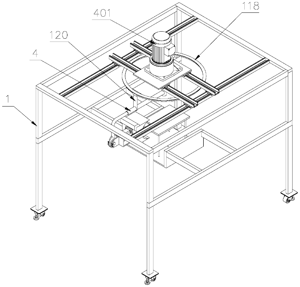
[0051] Please refer to Figure 1-3 , Figure 8 , Figure 12-13 ,

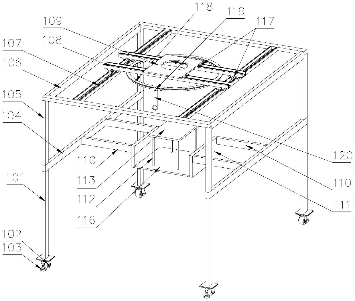
[0052] An automatic edge finding and edging device for special-shaped metal parts, including a support frame 1 and a driving device 4. The support frame 1 includes several legs 101, a first beam 104 connecting the upper ends of the legs 101, and a first beam 104 arranged on the top of the first beam 104. column 105, the second crossbeam 106 connecting the top of the column 105, a bottom plate 116 is arranged between the first crossbeams 104 on both sides, and a connecting plate 111 is connected to both sides of the bottom plate 116, and the connecting plate 111 is connected to the connecting rod 110 through the connecting rod 110. The inner wall of the first beam 104 is fixedly connected; one side of the upper part of the bottom plate 116 is connected with a supporting plate 113 through several support columns 112, and the workpiece 6 is placed on the upper part of the supporting plate 113; the second beam 10...

Embodiment 2

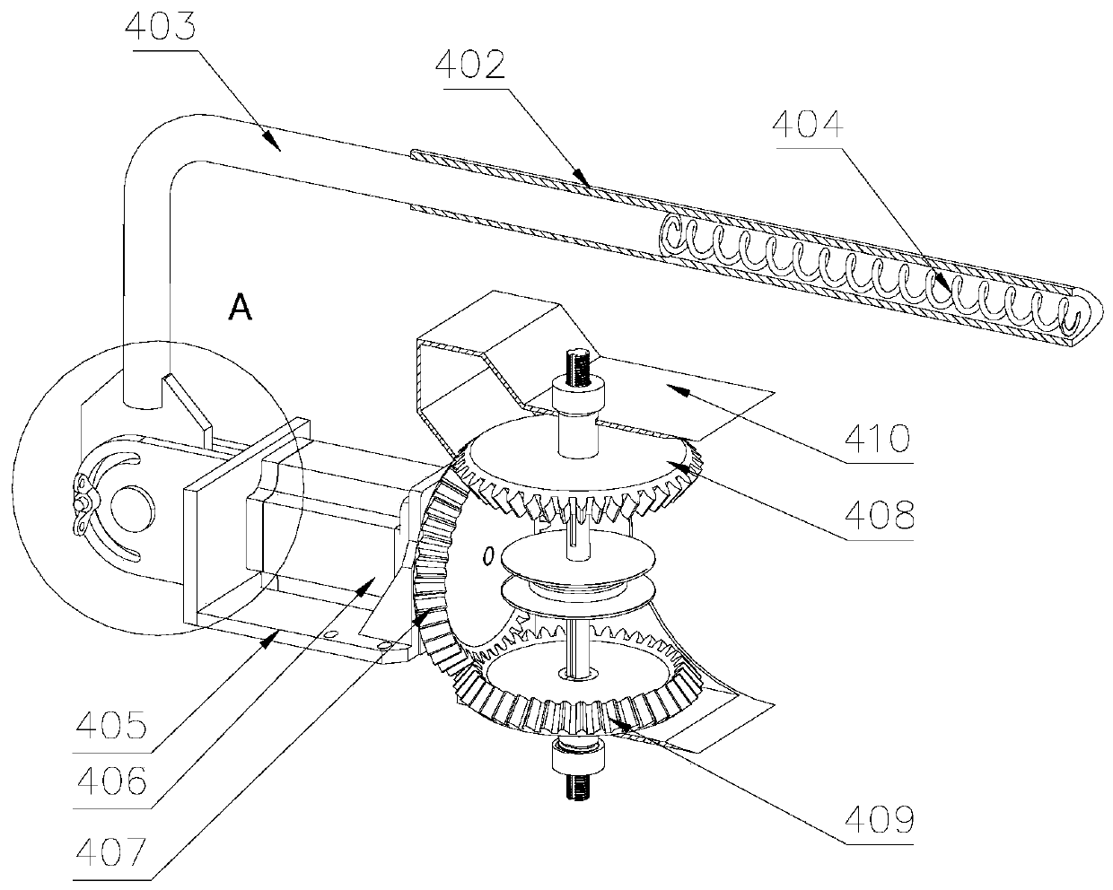
[0058] Please refer to Figure 4 , the difference from Example 1 is that

[0059] In this embodiment, a plurality of first rollers 114 are movably connected between the first beams 104 on both sides, and a plurality of second rollers 115 are movably connected between the first beam 104 and the connecting plate 111. The first rollers 114 and The second roller 115 facilitates the movement of the workpiece 6 on the support frame 1 , which reduces the labor intensity of the workers for lifting the workpiece 6 .

Embodiment 3

[0061] Please refer to Figure 5-6 , the difference from Example 2 is that

[0062]In this embodiment, the lower side of the bottom plate 116 is also provided with a lifting device 2, and the lifting device 2 includes a second motor seat 201 arranged at the lower end of the bottom plate 116, a second motor seat 201 arranged on the second motor seat 201 202, the output shaft of the second motor 202 is connected with a driving pulley 203, the center of the bottom plate 116 is provided with a base 205, one side of the base 205 is movably connected with a driven pulley 204, and the driving pulley 203 is connected with the driven pulley 204 through a belt, and the center of the driven pulley 204 is provided with a threaded hole, and a screw 206 is arranged inside the threaded hole, and one end of the screw 206 is connected with the supporting plate 113; the lower end of the supporting column 112 runs through the bottom plate 116 and connected with the bottom plate 116 in a gap, th...


PUM


Abstract

The invention discloses an automatic edge finding and grinding device for a specially shaped metal part. The automatic edge finding and grinding device comprises a support frame and a driving device;the support frame comprises a plurality of support legs, first cross beams connected with the upper ends of the support legs, vertical columns arranged at the upper parts of the first cross beams, andsecond cross beams connected with the upper parts of the vertical columns; the driving device comprises a first motor installed at the upper part of a first motor base, a sleeve connected with an output shaft of the first motor, and a crank arm arranged in the sleeve, and the sleeve is internally provided with a tension spring; one side of a driving gear is provided with a first driven gear, andthe other side of the driving gear is provided with a second driven gear; and one end of a first rotating shaft is provided with grinding wheels, and one side of each grinding wheel is provided with atop wheel. According to the automatic edge finding and grinding device, the grinding wheels are arranged on the upper and lower side faces of a workpiece, and used for grinding the both sides of theworkpiece; one side of each grinding wheel is provided with the top wheel, and the top wheels are traveled around the contour of a specially shaped workpiece, so that the edge grinding device is usedfor automatically finding an edge around the specially shaped workpiece for grinding; and the grinding accuracy of the specially shaped workpiece is ensured, and the grinding efficiency of the specially shaped workpiece is improved.

Description

technical field [0001] The invention belongs to the technical field of mechanical processing, and in particular relates to an automatic edge finding and edging device for special-shaped metal parts. Background technique [0002] During the cutting and forming of the metal steel plate, burrs are easily generated on the four sides of the metal steel plate. In order to ensure the processing quality of the workpiece, the burrs need to be polished. The existing burr grinding work generally uses a grinder to grind around the edge of the workpiece. After the side surface, hoist or flip the workpiece and then polish the lower side of the workpiece; due to the constant change of hand-held strength during manual grinding, it is easy to cause defects such as grinding pits on the edge of the workpiece, and the technical requirements for the operator are high; In addition, For special-shaped workpieces, due to their tortuous and changeable contours, grinding takes a long time, which affe...

Claims


Application Information

Patent Timeline
Patent Type & Authority Applications(China)
IPC IPC(8): B24B9/04B24B41/02B24B41/06B24B55/06
CPCB24B9/04B24B41/02B24B41/06B24B55/06
Inventor 张广传
Owner 济南工程职业技术学院
Why Eureka
Try Eureka