An adjustable angle marble cutting equipment

A cutting equipment and marble technology, applied in stone processing equipment, stone processing tools, work accessories, etc., can solve the problems of inability to adjust the cutting angle, easy displacement of marble, cumbersome operation procedures, etc., to avoid displacement and reduce complexity. , the effect of simple operation

Active Publication Date: 2022-03-25
济南森华精密机械有限公司
View PDF8 Cites 0 Cited by
  • Summary
  • Abstract
  • Description
  • Claims
  • Application Information

AI Technical Summary

Problems solved by technology

[0005] In order to overcome the disadvantages that the existing marble cutting table cannot adjust the cutting angle, the marble is easy to shift during cutting, and the operating procedures are very cumbersome and inefficient. Therefore, the technical problem of the present invention is: to provide an adjustable cutting angle that can An adjustable angle marble cutting device that fixes the marble firmly and prevents the marble from shifting during cutting

Method used


Image

  • An adjustable angle marble cutting equipment
  • An adjustable angle marble cutting equipment
  • An adjustable angle marble cutting equipment

Examples


Embodiment 1

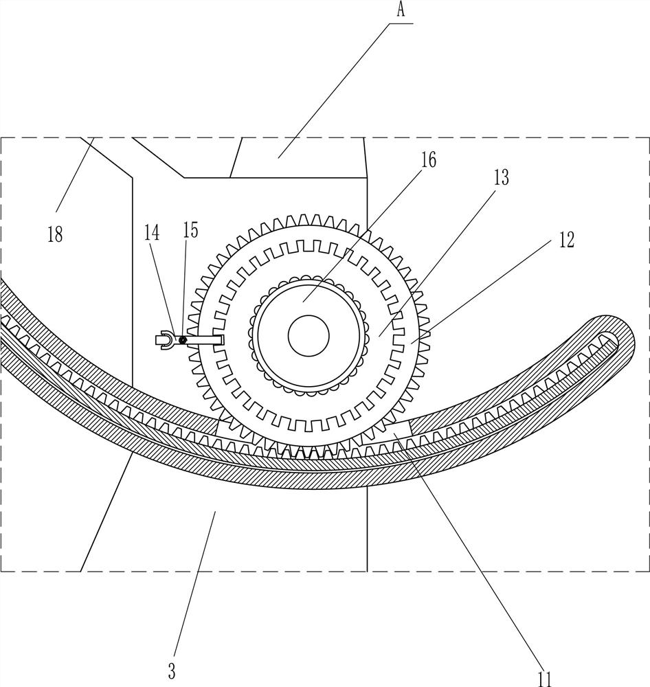
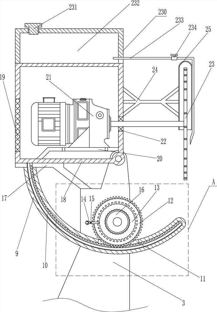
[0020] An adjustable angle marble cutting equipment, such as Figure 1-3 As shown, it includes a bottom plate 1, a first bracket 2, a second bracket 3, a conical plate 4, a first placing plate 5, a handle 8, an adjustment assembly, a support plate 17, a first frame body 18, a screen plate 19, a first plate Two placing plate 20, motor 21, bearing seat 22, cutting piece 23, first fixing rod 24 and waterproof cover 25, a first bracket 2 is symmetrically provided on the top right side of the bottom plate 1, and the bottom plate 1 is connected with the first bracket by welding 2 is connected, a second bracket 3 is arranged on the top left of the bottom plate 1, a conical plate 4 is arranged on the top of the first bracket 2, a first placing plate 5 is placed on the top of the conical plate 4, and the left and right sides of the bottom of the first placing plate 5 are placed. A conical groove 6 is opened, and the conical groove 6 is slidably matched with the conical plate 4. A handl...

Embodiment 2

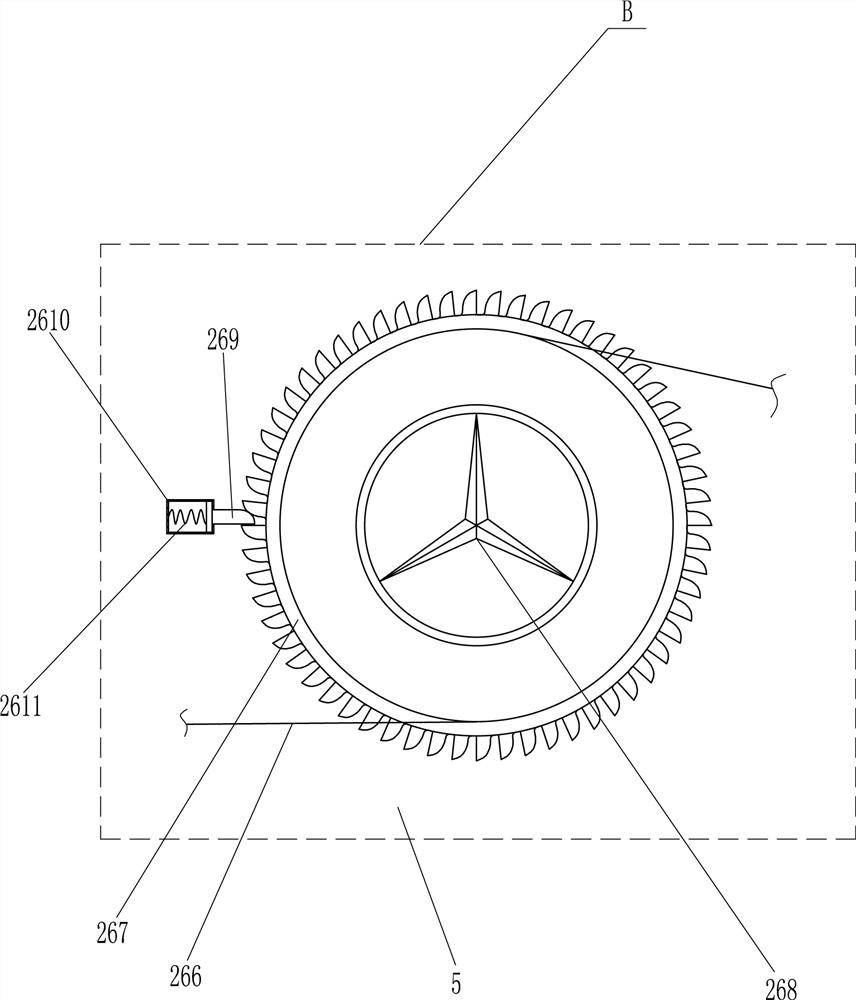
[0024]It also includes a fixing device 26. The fixing device 26 includes a housing 261, a second fixing rod 262, a first spring 263, a horizontal plate 264, a pulley 265, a pulling rope 266, a ratchet wheel 267, a second hand wheel 268, a ratchet tooth The block 269, the second frame 2610 and the second spring 2611, the left and right sides of the front side of the first placing plate 5 are symmetrically provided with a casing 261, and the first placing plate 5 is connected to the casing 261 by welding. A second fixing rod 262 is slidably arranged in the body 261 , a first spring 263 is connected to the bottom of the second fixing rod 262 , a transverse plate 264 is installed in the lower part of the housing 261 , and the tail end of the first spring 263 is connected to the middle of the top of the transverse plate 264 , a pulley 265 is installed in the lower part of the housing 261, a pulling rope 266 is connected to the bottom of the second fixing rod 262, a ratchet wheel 267...

Embodiment 3

[0027] It also includes a cooling and dust-reducing mechanism 230. The cooling and dust-reducing mechanism 230 includes a plug 231, a water tank 232, a water outlet pipe 233 and a valve 234. The top of the first frame body 18 is provided with a water tank 232. The first frame body 18 is connected to the water tank by welding. 232 is connected, a plug 231 is provided on the left side of the top of the first frame body 18, a water outlet pipe 233 is connected to the lower right side of the water tank 232, the end of the water outlet pipe 233 is located on the right side of the waterproof cover 25, and the water outlet pipe 233 is provided with a valve 234.

[0028] The operator opens the plug 231 to fill the water tank 232 with clean water, and then plugs the plug 231. When it is necessary to reduce dust during cutting or to cool the cutting blade 23, open the valve 234, and then the water in the water tank 232 will pass through the water outlet pipe 233. It drips onto the cuttin...


PUM


Abstract

The invention relates to a cutting device, in particular to an angle-adjustable marble cutting device. Therefore, the technical problem of the present invention is to provide an angle-adjustable marble cutting device that can adjust the cutting angle, can fix the marble firmly, and avoid the displacement of the marble during cutting. Technical solution: An angle-adjustable marble cutting equipment, including a bottom plate, a first bracket, a second bracket, a tapered plate, etc.; the first bracket is symmetrically arranged on the right side of the top of the bottom plate, and the second bracket is arranged on the left side of the top of the bottom plate . The invention can adjust the angle of the motor and the cutting piece by turning the first hand wheel, thereby adjusting the cutting angle of the marble, so that the angle can be adjusted when the marble is cut, and the operation of adjusting the angle is relatively simple, and the angle of adjustment is relatively wide. It can be adjusted according to the cutting needs, avoiding the subsequent use of the hand grinder for secondary cutting, which improves the work efficiency and reduces the complexity of the operation.

Description

technical field [0001] The invention relates to a cutting device, in particular to a marble cutting device with an adjustable angle. Background technique [0002] With the improvement of people's living standards, the material requirements are getting higher and higher. In order to make their houses more beautiful and luxurious, people will decorate their houses. At present, there are many kinds of decoration materials, among which high-end wall and floor decoration The material is mainly marble, especially for high-end residential areas and villas. Marble is used as the raw material for decoration. Large pieces of marble need to be cut during decoration. Marble is particularly hard, so the requirements for marble cutting equipment are high. [0003] At present, the cutting of marble is usually carried out by using a large stone edge trimmer, which has a large volume and cannot adjust the cutting angle. When cutting, only the vertical plane can be cut. When the inclined plan...

Claims


Application Information

Patent Timeline
Patent Type & Authority Patents(China)
IPC IPC(8): B28D1/22B28D7/02B28D7/04B28D7/00
CPCB28D1/22B28D7/02B28D7/04B28D7/00
Inventor 许家竣
Owner 济南森华精密机械有限公司
Why Eureka
Try Eureka