A floor drain type drainage device for aluminum alloy ships

A drainage device and aluminum alloy technology, which is applied in the direction of ship soil drainage, water supply devices, drainage structures, etc., can solve the problems of cleaning, floor drain drainage device blockage, filter screen lack of limit structure, etc., so as to improve drainage efficiency and avoid accumulation water effect

Active Publication Date: 2020-10-16
嵊州市汇业新材料科技有限公司
View PDF1 Cites 0 Cited by
  • Summary
  • Abstract
  • Description
  • Claims
  • Application Information

AI Technical Summary

Problems solved by technology

[0005] In order to solve the above technical problems, the present invention provides a floor drain type drainage device for aluminum alloy ships to solve the following deficiencies in the actual use of the existing floor drain type drainage device, such as: 1. The floor drain type in the bathroom The filter screen on the drainage device often filters out many hairs produced during shampooing, and when the filter screen is covered with hairs, it is easy to cause blockage on the upper surface of the floor drain type drainage device, and when people are washing their hair, they cannot It is convenient to remove the hair on the filter net, so that when people wash their hair, there will be a lot of accumulated water on the bathroom floor, which will soak people's shoes and bring a lot of inconvenience to the hair washing personnel; 2. Due to the existing floor drain type drainage The filter on the device lacks an effective limit structure, so that naughty children can easily remove the filter, and naughty children may also put some large paper towels and other blockages into the floor drain In the device, which in turn causes the problem of the internal blockage of the floor drain type drainage device

Method used


Image

  • A floor drain type drainage device for aluminum alloy ships
  • A floor drain type drainage device for aluminum alloy ships
  • A floor drain type drainage device for aluminum alloy ships

Examples


Embodiment

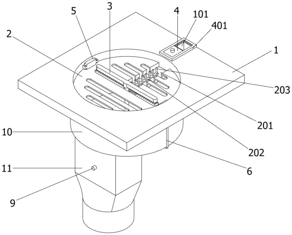
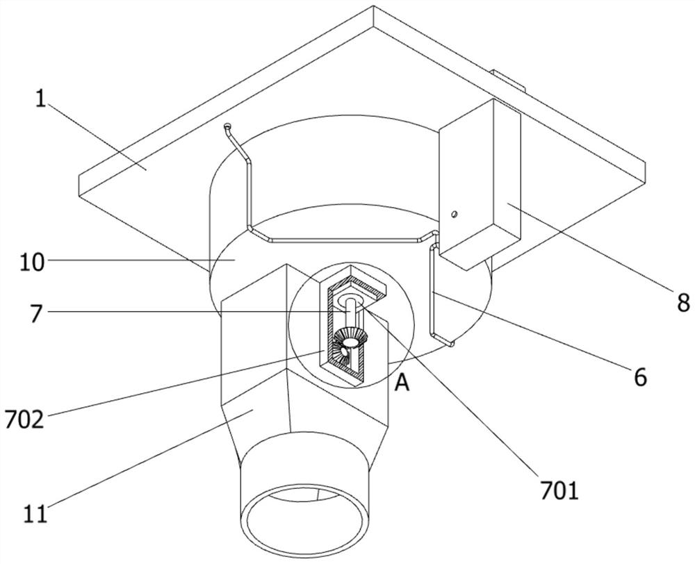
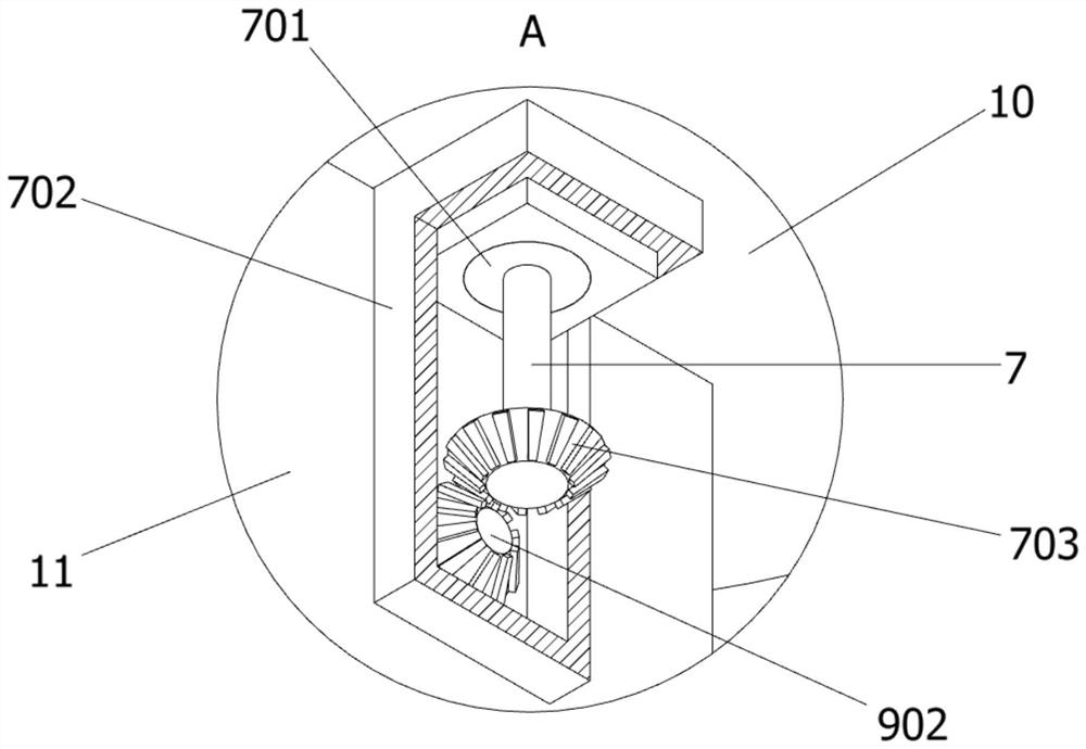
[0035] as attached figure 1 to attach Figure 11 Shown:

[0036] The present invention provides a floor drain type drainage device for aluminum alloy ships, comprising: a floor drain base plate 1, a circular water drop box 10 is provided at the bottom of the floor drain base plate 1, and an inner peripheral surface of the circular water drop box 10 is provided on the upper surface of the floor drain base plate 1 A circular water inlet with the same size. The floor drain base plate 1 also includes a rectangular opening 101, a limit mechanism chute 102, a pulley 103 and an annular groove 104. The upper end of the floor drain base plate 1 is located at the sealing shield plate 4. A rectangular opening is opened 101, and the interior of the rectangular port 101 communicates with the interior of the protection mechanism 8, and the interior of the floor drain substrate 1 is symmetrically provided with two limit mechanism chutes 102, and each limit mechanism chute 102 is provided wi...


PUM


Abstract

The invention provides a floor drain type drainage device for an aluminum alloy ship. The device comprises a floor drain base plate having the bottom with a circular water falling box. With a cleaningmechanism, when water in the circular water falling box flows into a sewer pipe, a water wheel begins to rotate under the action of impact force of water and a second bevel gear at the rear end of adriving mechanism is driven to rotate; and then a transmission mechanism is driven to rotate, so that the cleaning mechanism rotates at the upper part of a filter screen; with the brush of the cleaning mechanism, hair distributed on the upper end surface of the filter screen is brought into a rectangular groove; meanwhile, a hair scraping column is matched and hair attached to the brush of the cleaning mechanism is removed and the removed hair falls into the rectangular groove, so that most space of the upper end face of the filter screen is not full of hair. Therefore, the drainage efficiencyof the floor drain type drainage device is improved, and a phenomenon that a large amount of water is accumulated on the ground of a bathroom when people wash hair is effectively avoided.

Description

technical field [0001] The invention belongs to the technical field of drainage devices, and more specifically relates to a floor drain type drainage device for aluminum alloy ships. Background technique [0002] The floor drain is an important interface connecting the drainage pipe system and the indoor floor. As an important part of the drainage system in the residence, its performance directly affects the quality of the indoor air, and is very important for the odor control in the bathroom. The main functions of the floor drain: anti-odor, anti-clogging, anti-cockroach, anti-virus, anti-return water, anti-drying. [0003] For example, application number: CN201810743149.7 The present invention discloses an anti-blocking floor drain drainage structure for shower rooms, which belongs to the field of floor drain drainage equipment, and includes a floor drain base and a floor drain core for drainage. The floor drain core is lapped on the floor drain base In the seat, a floor ...

Claims


Application Information

Patent Timeline
Patent Type & Authority Patents(China)
IPC IPC(8): B63B29/16E03F5/04E03F5/14
CPCB63B29/16E03F5/0407E03F5/0408E03F5/041E03F5/14
Inventor 瞿永顺
Owner 嵊州市汇业新材料科技有限公司
Why Eureka
Try Eureka