
Steel-concrete composite structure continuous box girder and manufacturing method thereof

A combined structure and concrete technology, used in bridges, bridge parts, bridge construction, etc., can solve the problems of limited pre-compression stress, increase the shear stress at the junction of concrete and steel beams, and affect the crack resistance of the concrete roof. Quantity, reducing construction time and construction cost, and the effect of reasonable stress

Active Publication Date: 2020-04-17
SOUTHEAST UNIV
View PDF22 Cites 2 Cited by
  • Summary
  • Abstract
  • Description
  • Claims
  • Application Information

AI Technical Summary

Problems solved by technology

However, the prestress applied to the roof concrete in the negative moment area increases the shear stress at the junction of the concrete and the steel beam, and since the elastic modulus of the flat steel web is greater than the concrete elastic modulus, the prestress applied in the negative moment area is large Part of it is consumed on the steel web and steel flange, and the actual effective precompression stress applied to the roof concrete is very limited, which greatly affects the crack resistance of the concrete roof

Method used


Image

  • Steel-concrete composite structure continuous box girder and manufacturing method thereof
  • Steel-concrete composite structure continuous box girder and manufacturing method thereof
  • Steel-concrete composite structure continuous box girder and manufacturing method thereof

Examples


Embodiment Construction

[0032] In order to facilitate the understanding of the present invention, the present invention will be described more fully below with reference to the associated drawings.

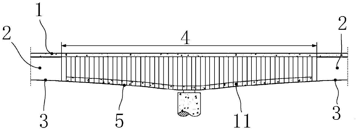
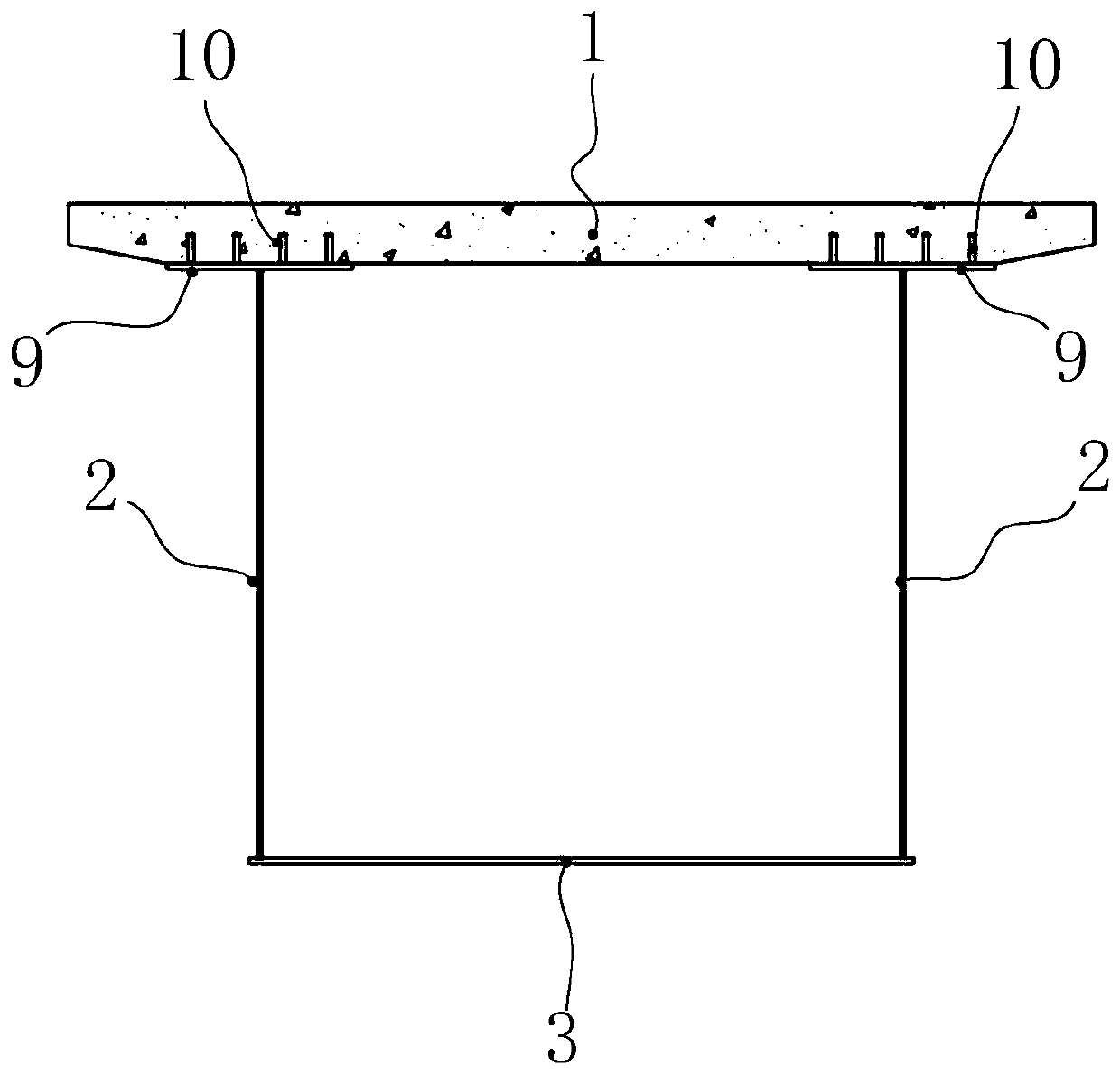
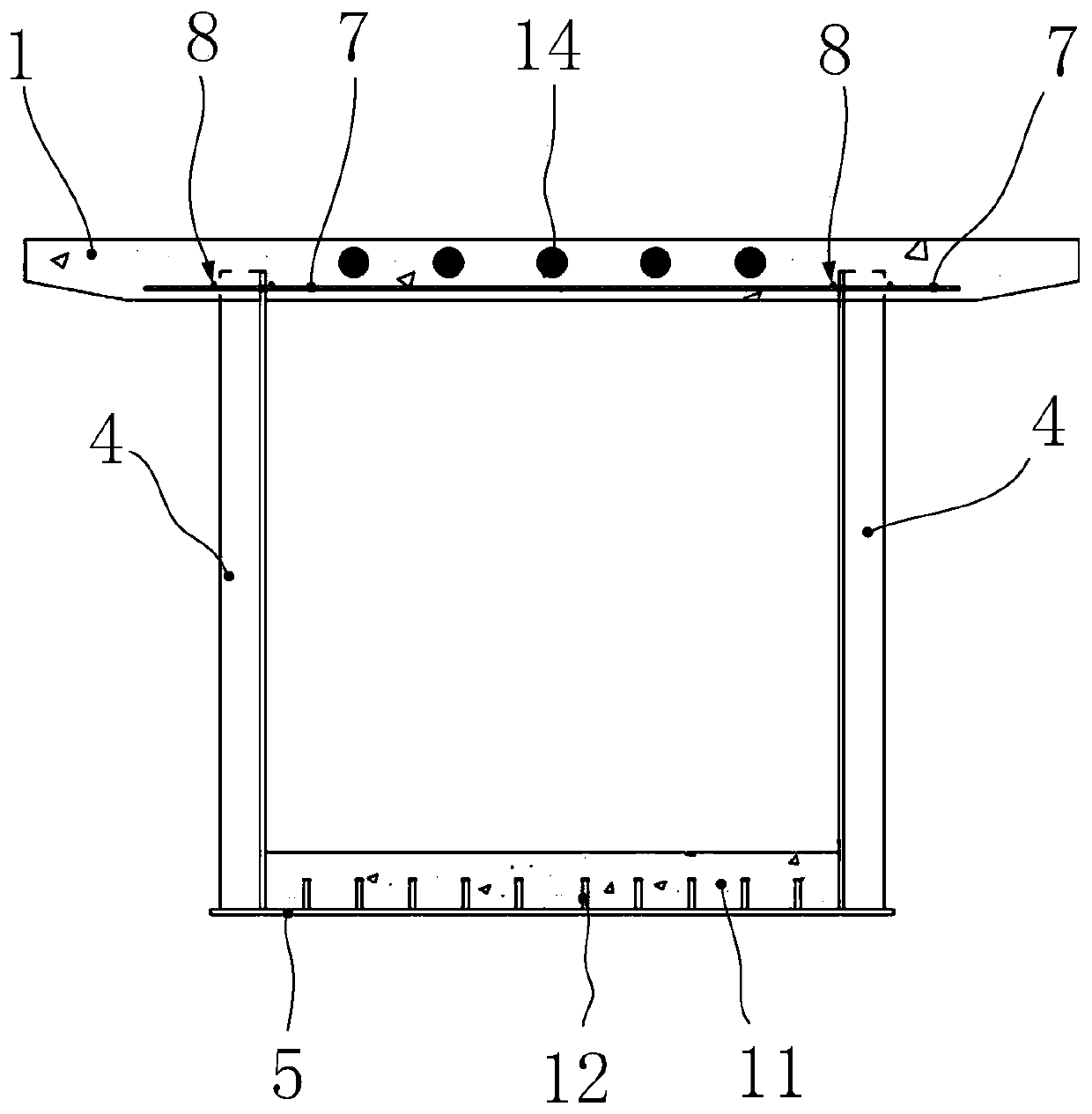
[0033] Such as Figure 1-7 As shown, a continuous box girder with steel-concrete composite structure includes a concrete roof 1, a steel box in the positive moment zone located in the mid-span region of the continuous beam, a steel box in the negative moment zone spanning the middle fulcrum of the continuous beam, and a steel box Connection plate 13. The steel box in the negative bending moment area is set in the negative bending moment area of ​​the middle fulcrum, and the steel box in the positive bending moment area is connected to both ends of the steel box in the negative bending moment area.

[0034] Specifically, see figure 2 , the steel box in the positive bending moment area includes two flat steel webs 2 arranged in parallel, the first bottom plate 3 welded on the bottom of the two flat stee...


PUM


Abstract

The invention discloses a steel-concrete composite structure continuous box girder and a manufacturing method thereof, and belongs to the technical field of bridge structures. The continuous box girder still adopts a flat steel web in a sagging moment area, but adopts a corrugated steel web to replace a conventional flat steel web in a middle fulcrum hogging moment area, adopts an embedded PBL shear connector to connect the corrugated steel web and a concrete top plate, and is filled with an elastic material between the outer sides of a wave crest section and a wave trough section of the corrugated steel web and a concrete contact surface to form a reserved deformation buffer area. Once prestress is applied to the hogging moment area, compressive deformation is prone to occurring under pressure due to the fact that the longitudinal rigidity of the corrugated steel web is small, and meanwhile, the elastic material allows the corrugated steel web to transversely expand and deform. By means of the combined action of the two factors, the pre-pressing stress can be effectively applied to the concrete top plate, and the prestress applying efficiency is effectively improved. The compositestructure effectively relieves the possibility of concrete cracking in the hogging moment area, and the safety and durability of the bridge are improved.

Description

technical field [0001] The invention belongs to the technical field of bridge structures, and in particular relates to a steel-concrete composite structure continuous box girder and a manufacturing method thereof. Background technique [0002] The steel-concrete composite structure simply supported beam takes advantage of the compressive strength of concrete, and replaces the concrete in the mid-span tension zone with a steel structure, which effectively avoids the cracking of the lower concrete. However, the main girder in the negative moment zone of the steel-concrete composite continuous girder bridge is in an unfavorable stress state where the steel girder is under compression and the concrete bridge deck is under tension. The bridge deck concrete bears a large tensile stress and is prone to cracking, which leads to a decrease in structural stiffness. At the same time, the steel beams in the compression area also have stability problems. Therefore, in practical engineer...

Claims


Application Information

Patent Timeline
Patent Type & Authority Applications(China)
IPC IPC(8): E01D19/00E01D2/04E01D21/00
CPCE01D2/04E01D19/00E01D21/00
Inventor 吴文清何冬晨周逸松戴金希石中琦王新雅刘泓佚
Owner SOUTHEAST UNIV
Learn More