
Energy-dissipation self-resetting beam and column joint connection device of steel structure

A beam-column joint and connecting device technology, which is applied to building components, building structures, building types, etc., can solve the problems of poor self-reset ability, difficult to repair, and prone to plastic deformation, and achieves a high degree of installation, simple structure, Easy and fast construction

Active Publication Date: 2020-04-17
YANSHAN UNIV
View PDF5 Cites 9 Cited by
  • Summary
  • Abstract
  • Description
  • Claims
  • Application Information

AI Technical Summary

Problems solved by technology

[0003] The steel structure has the advantages of high strength, good seismic performance, and short construction period, and is widely used in various buildings; the beam-column joint is a key component in the steel structure, which ensures the cooperative work of the beam-column and makes the structure form However, the traditional beam-column joints of steel structures rely on the plastic deformation of the components themselves to dissipate energy, have poor self-resetting ability, and are prone to plastic deformation in earthquakes and are difficult to repair.

Method used


Image

  • Energy-dissipation self-resetting beam and column joint connection device of steel structure
  • Energy-dissipation self-resetting beam and column joint connection device of steel structure
  • Energy-dissipation self-resetting beam and column joint connection device of steel structure

Examples


Embodiment Construction

[0023] In order to more clearly illustrate the technical solutions in the embodiments of the present invention or the prior art, the following will briefly introduce the drawings that need to be used in the description of the embodiments or the prior art. Obviously, the accompanying drawings in the following description These are some embodiments of the present invention. Those skilled in the art can also obtain other drawings based on these drawings without creative work.

[0024] It should be noted that in the description of the present invention, the terms "upper", "lower", "top", "bottom", "side", "other side", "left", "right" etc. indicate The orientation or positional relationship is based on the orientation or positional relationship shown in the drawings, and is only for the convenience of describing the present invention and simplification of the description, and does not mean that devices or elements must have a specific orientation, be constructed and operated in a s...


PUM

PropertyMeasurementUnit
Yield strengthaaaaaaaaaa

Abstract

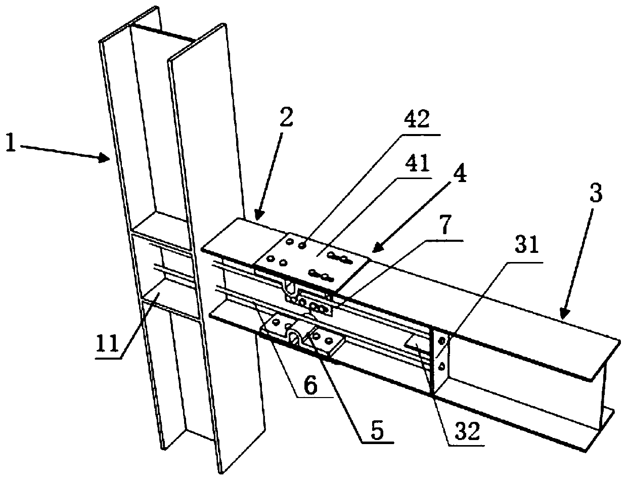
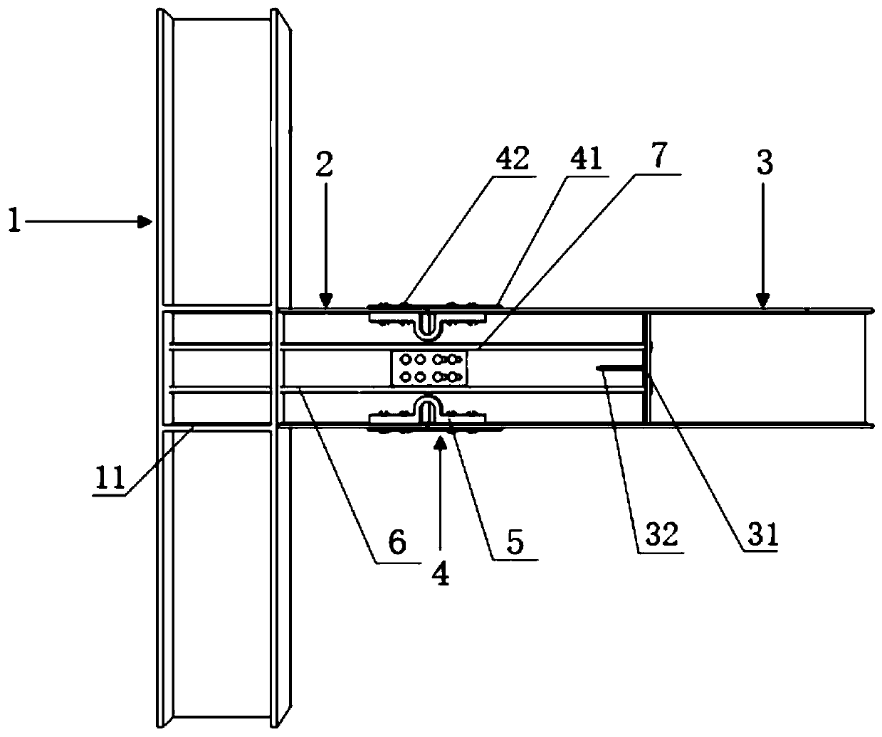
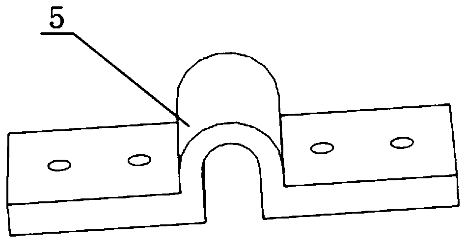
The invention relates to an energy-dissipation self-resetting beam and column joint connection device of a steel structure. The device comprises a steel frame column, a short cantilever beam just connected to one side of the steel frame column and a connecting beam spliced at the other end of the short cantilever beam, wherein the flange and web splices of the connecting beam and the short cantilever beam are connected through energy dissipation connection components, and a U-shaped steel damper is arranged on the inner side of the flange splice of the connecting beam and the short cantileverbeam; a group of anchor plates is respectively arranged at the symmetrical positions of the two sides of a web of the connecting beam; and the steel frame column is connected with the upper side and the lower side of each anchor plate through prestressed steel bars arranged in a horizontal direction. The U-shaped steel damper dissipates energy at the splices of the short cantilever beam and the connecting beam to ensure that the beam and column bodies keep the elasticity from being broken. Moreover, the structure is simple, most of the structure is bolted, the modularity degree is high, disassembly, replacement and repair are easy, the construction is convenient, and the device conforms to the development trend of the construction industry. Meanwhile, the prestressed steel bars can provideself-restoring force and have an ideal self-resetting effect.

Description

technical field [0001] The invention relates to the technical field of energy dissipation and shock absorption of building structures, in particular to an energy dissipation self-resetting steel structure beam-column joint connection device. Background technique [0002] In recent years, scholars at home and abroad have successively proposed a new type of energy-consuming self-resetting structure to solve the problem of collapse of buildings due to excessive residual deformation after the earthquake, so that the building has a recovery function and can be restored to normal use after the earthquake. It has received great attention and in-depth research from the international earthquake engineering community. [0003] The steel structure has the advantages of high strength, good seismic performance, and short construction period, and is widely used in various buildings; the beam-column joint is a key component in the steel structure, which ensures the cooperative work of the ...

Claims


Application Information

Patent Timeline
IPC IPC(8): E04B1/24E04B1/58E04H9/02E04B1/98
CPCE04B1/24E04B1/2403E04B1/98E04B2001/2406E04H9/021E04H9/024
Inventor 刘建明夏学通宋涛
Owner YANSHAN UNIV
Learn More