Hydraulic inertia-capacitance balance tuning vibration damping device

A vibration damping device and balancing technology, applied in building types, buildings, building components, etc., can solve the problems of increased consumption cost, complex vibration response, and can not be too small, so as to improve energy consumption capacity, expand the scope of vibration reduction, guarantee The effect of reliability

Active Publication Date: 2020-04-17
SHANDONG UNIV
View PDF3 Cites 7 Cited by
  • Summary
  • Abstract
  • Description
  • Claims
  • Application Information

AI Technical Summary

Problems solved by technology

However, for high-rise structures or long-span structures, there is often a huge mass, and the additional mass of the vibration damping device cannot be too small if the optimal mass ratio is satisfied
However, large mass elements may change the dynamic...

Method used


Image

  • Hydraulic inertia-capacitance balance tuning vibration damping device
  • Hydraulic inertia-capacitance balance tuning vibration damping device
  • Hydraulic inertia-capacitance balance tuning vibration damping device

Examples


Embodiment Construction

[0040] It should be pointed out that the following detailed description is exemplary and intended to provide further explanation to the present application. Unless defined otherwise, all technical and scientific terms used herein have the same meaning as commonly understood by one of ordinary skill in the art to which this application belongs.

[0041] It should be noted that the terminology used here is only for describing specific implementations, and is not intended to limit the exemplary implementations according to the present application. As used herein, unless the invention clearly states otherwise, the singular form is also intended to include the plural form. In addition, it should also be understood that when the terms "comprising" and / or "comprising" are used in this specification, their Indicate the presence of features, steps, operations, means, components and / or combinations thereof;

[0042] For the convenience of description, if the words "up", "down", "left" ...


PUM


Abstract

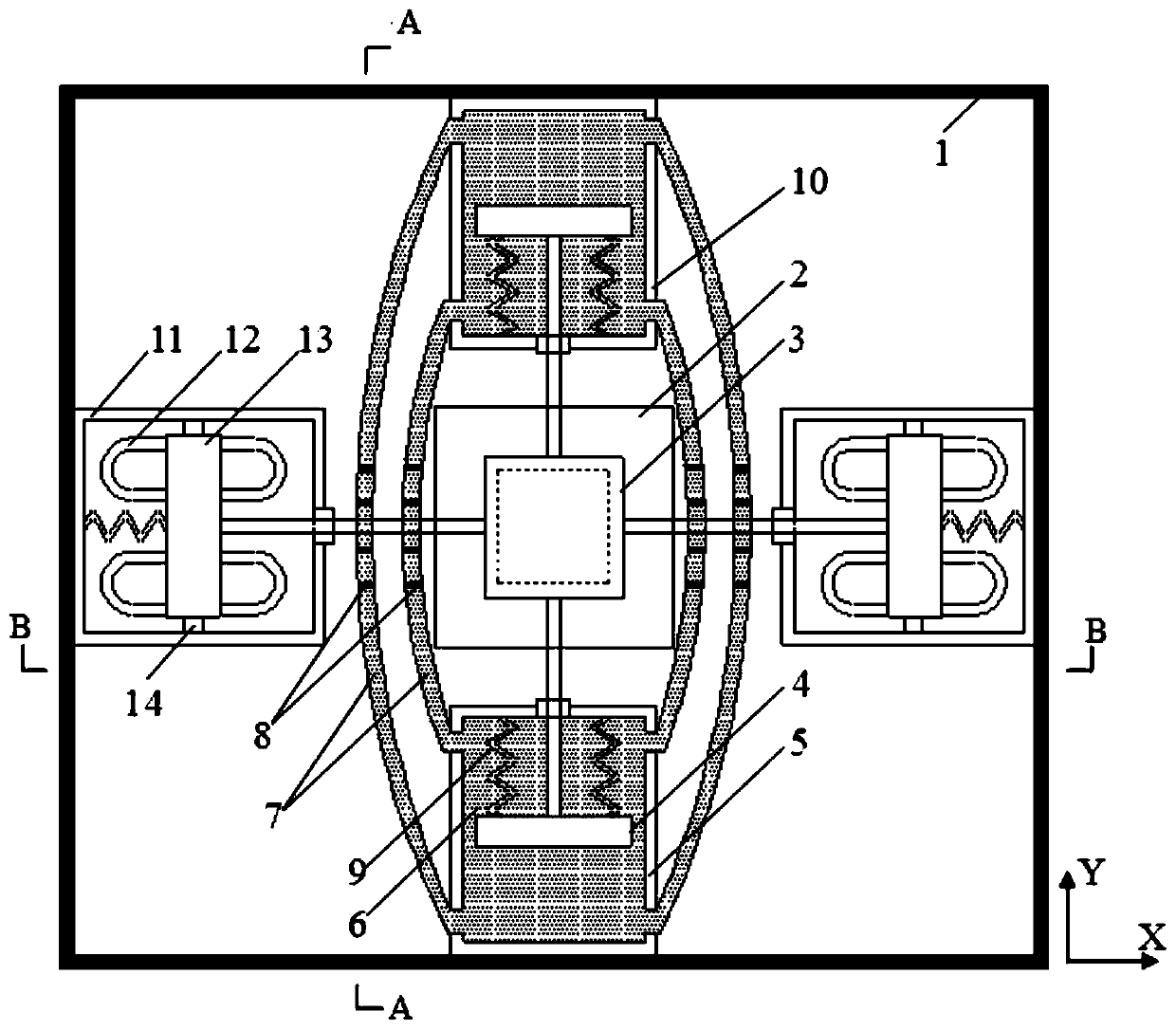
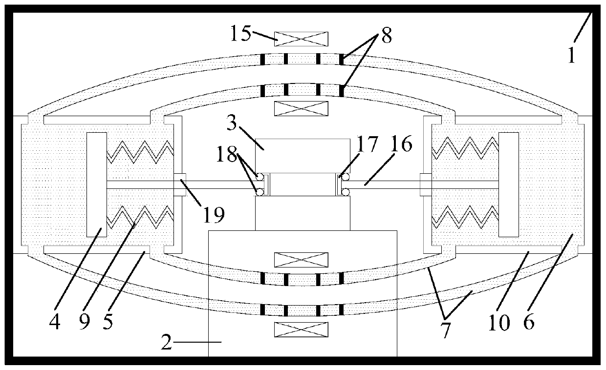
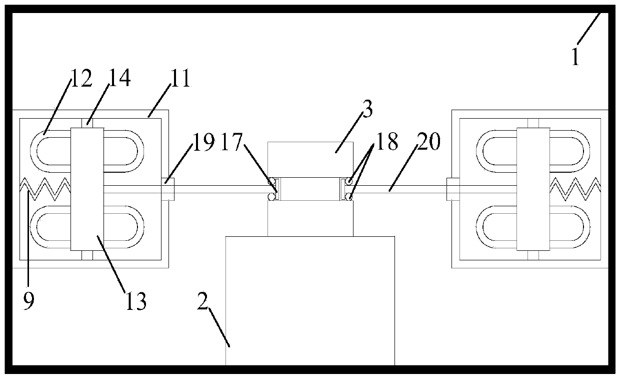
The invention discloses a hydraulic inertia-capacitance balance tuning vibration damping device. The vibration damping device comprises a protective cylinder. A mass block is arranged inside the protective cylinder. Two opposite side faces of the mass block are connected with 'inertia-capacitance-damping' vibration damping units, the other two opposite side faces of the mass block are each connected with a positive-negative rigidity parallel-connection unit. Each 'inertia-capacitance-damping' vibration damping unit comprises two vibration damping cavities, a piston rod, a piston, a curved tubeand an induction control device, wherein the two vibration damping cavities communicate with each other through the curved tube, a power-on coil is wound around the local area of the curved tube, andthe power-on coil is connected with the induction control device; the mass block is connected with the pistons located in the vibration damping cavities through the piston rods. The two positive-negative rigidity parallel-connection units are located at the two sides of the mass block. Each positive-negative rigidity parallel-connection unit comprises an insulation cylinder, a magnet and a U-shaped soft steel bar. The mass block is connected with two rigidity rods. The two rigidity rods extend into the two insulation cylinders respectively to be connected with a linkage block. Two sleeved annular magnets are arranged inside each insulation cylinder. The two annular magnets are connected through U-shaped soft steel bars. The linkage blocks are connected with the annular magnet located at the inner ring.

Description

technical field [0001] The invention belongs to the field of vibration control of civil engineering, and in particular relates to a hydraulic inertial capacity balance tuning vibration damping device, which is mainly used in controlling the vibration response of high-rise buildings and towering structures. Background technique [0002] In actual engineering, structural strength is often increased by increasing the size of load-bearing components, or structural ductility is considered through cracking and failure of structural components, thereby improving the seismic performance of buildings. Traditional seismic design ideas not only increase material costs, but also make post-earthquake repairs extremely difficult. Based on this, the introduction of vibration control theory into structural engineering will transform the structural design from the simple anti-seismic design stage to the shock-absorbing design stage, which has broad application prospects. [0003] The curren...

Claims


Application Information

Patent Timeline
IPC IPC(8): E04B1/98E04H9/02E04H9/14
CPCE04H9/021E04H9/14
Inventor 刘俊才田利杨礼东付朝阳
Owner SHANDONG UNIV
Why Eureka
Try Eureka