Automatic-control ash removal device for boiler in thermal power plant

A technology for cleaning devices and thermal power plants, applied to lighting and heating equipment, etc., can solve problems such as increased labor intensity of workers, insufficient combustion of combustibles, and impact on air quality, so as to facilitate fuel injection, increase cleanliness, and avoid flying Effect

Inactive Publication Date: 2020-04-17
西安沃唯隆控制系统有限公司
View PDF1 Cites 2 Cited by
  • Summary
  • Abstract
  • Description
  • Claims
  • Application Information

AI Technical Summary

Problems solved by technology

[0003] According to the patent application number 201520738521.7, an energy-saving heating boiler is disclosed, which includes a furnace body, a heat exchange chamber, a combustion chamber, a waste material collection room and a chimney. The bottom of the furnace body is provided with a waste material collection room. Supporting legs, the other side of the waste collection chamber is provided with a miscellaneous removal door, a combustion chamber is arranged above the waste collection chamber, a grate is arranged between the combustion chamber and the waste collection chamber, and a feeding chamber is provided outside the combustion chamber above the miscellaneous removal door. The structure of the door is simple and reasonable, which facilitates the maintenance of the device in the later stage, reduces the waste of heat, and realizes the effect of energy saving. However, the waste residue falling on the waste collection still needs to be cleaned manually regularly, which will waste manpower resources, and it will cause ash to fly everywhere, affect the air quality, and can increase the labor intensity of the staff. If the ash removal is not handled in time, it will cause insufficient combustion of the combustibles. Therefore, it is necessary to provide a boiler for thermal power plant Dust automatic control cleaning device to solve the existing problems

Method used


Image

  • Automatic-control ash removal device for boiler in thermal power plant
  • Automatic-control ash removal device for boiler in thermal power plant

Examples


Embodiment 1

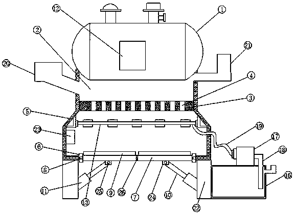
[0024] see Figure 1-2 According to an embodiment of the present invention, an automatic control and cleaning device for boiler dust in a thermal power plant includes a boiler body 1, a furnace 2 is provided at the bottom of the boiler body 1, and a combustion placement plate 3 is provided at the bottom of the furnace 2, The combustion placement plate 3 is provided with a plurality of through holes 4, the bottom side of the boiler body 1 is provided with a base 5, and the inside of the base 5 is provided with a cavity, between the cavity and the furnace 2 Connected by the through hole 4, the bottom of the base 5 is provided with a discharge port, both sides of the discharge port are fixed with a fixed plate 6, and one side of the fixed plate 6 is provided with a movable plate 7, so One side of the movable plate 7 is movably connected with the fixed plate 6 through a rotating shaft 8, one side of the movable plate 7 is fixedly provided with a pressure sensor 9, and the other si...

Embodiment 2

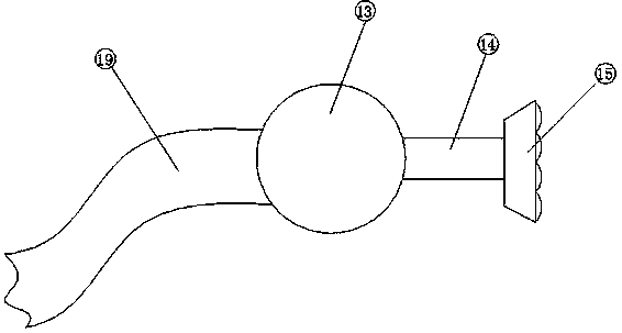
[0026] see Figure 1-2 , for the cavity, the interior of the cavity is provided with a spraying device, the spraying device includes a water main pipe 13, and one side of the water main pipe 13 is provided with several branch pipes 14, and the branch pipes 14 are far away from the One side of the main water pipe 13 is provided with a shower nozzle 15, and one end of the water main pipe 13 is connected with a water supply device, and the spray device can settle the dust produced by the combustion to avoid the flying of the dust.

Embodiment 3

[0028] For the water supply device, the water supply device includes a water tank 16, the top of the water tank 16 is provided with a water pump 17, one end of the water pump 17 is provided with an outlet pipe 18, and the other end of the water pump 17 is provided with a hose 19, The end of the flexible hose 19 away from the water pump 17 passes through the base 5 and communicates with the water main pipe 13 , the water supply device can provide water to the spraying device, and deliver the water from the water tank 16 to the spray head 15 .


PUM


Abstract

The invention discloses an automatic-control ash removal device for a boiler in a thermal power plant. The automatic-control ash removal device for the boiler in the thermal power plant comprises a boiler body. A hearth is arranged at the bottom of the boiler body. A combustion storage plate is arranged at the bottom of the hearth. A plurality of through holes are formed in the combustion storageplate. A base is arranged on one side of the boiler body. A cavity is formed in the base and communicates with the hearth through the through holes. A discharge outlet is formed in the bottom of the base. Fixed plates are fixedly arranged on the two sides of the discharge outlet. A movable plate is arranged on one side of each fixed plate. One side of each movable plate is movably connected with the corresponding fixed plate through a rotary shaft. A pressure sensor is arranged on one side of each movable plate. The automatic-control ash removal device for the boiler in the thermal power planthas the beneficial effects that the structure is simple, operation is convenient, and ash can be discharged automatically and does not need to be manually removed; and meanwhile, the influence of ashaccumulation on the combustion of combustible substances is avoided, the ash can be removed more conveniently, and normal combustion of the combustible substances in the hearth is guaranteed.

Description

technical field [0001] The invention relates to the field of boiler design in a thermal power plant, in particular to an automatic control and cleaning device for boiler dust in a thermal power plant. Background technique [0002] In the current field of boiler dust removal, boilers as power machinery began to be widely used in my country in the late 1970s. It has become a replacement product for electric heat sources and traditional steam power heat sources in many industries. Converting heat energy, when the boiler uses combustion materials for combustion, a large amount of waste residue will be generated inside the furnace, and the accumulation of waste residue after long-term use will affect the normal combustion of combustion materials inside the furnace. [0003] According to the patent application number 201520738521.7, an energy-saving heating boiler is disclosed, which includes a furnace body, a heat exchange chamber, a combustion chamber, a waste material collection...

Claims


Application Information

Patent Timeline
Patent Type & Authority Applications(China)
IPC IPC(8): F23J1/06F23J15/04
CPCF23J1/06F23J15/04
Inventor 周思杰
Owner 西安沃唯隆控制系统有限公司
Why Eureka
Try Eureka