
A diesel engine radiator

An engine and radiator technology, which is applied in the cooling of engine components, machines/engines, and engines, can solve the problems that the radiator cannot meet the cooling requirements, affects the service life of the engine, and has a slow cooling speed, and achieves a simple and practical structure. High performance, good cooling effect

Active Publication Date: 2021-04-20
QUANJIAO SAIDELI MACHINERY
View PDF9 Cites 0 Cited by
  • Summary
  • Abstract
  • Description
  • Claims
  • Application Information

AI Technical Summary

Problems solved by technology

[0003] Existing diesel engine radiators only rely on heat dissipation pipes for heat dissipation, which has low heat dissipation efficiency and slow heat dissipation speed, and after the engine has been working for a long time, or in hot weather, the radiator can no longer meet the heat dissipation requirements. Cooling requirements will affect the normal operation of the entire engine. If the cooling effect of the engine is not good, it will directly affect the service life of the engine

Method used


Image

  • A diesel engine radiator
  • A diesel engine radiator
  • A diesel engine radiator

Examples


Embodiment 1

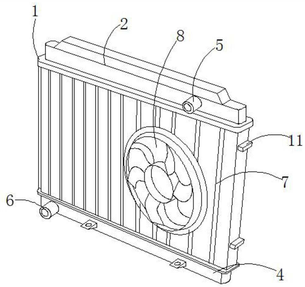
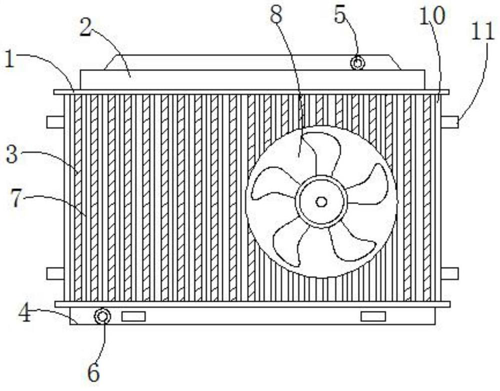
[0026] Such as Figure 1-4 As shown, a diesel engine radiator includes a frame 1, an upper water chamber 2, a cooling pipe 3 and a lower water chamber 4, the upper water chamber 2 is located at the upper end of the frame 1, and the upper side wall of the upper water chamber 2 is provided with The water inlet pipe 5 and the heat dissipation pipe 3 are located between the upper and lower racks 1, the lower water chamber 4 is fixedly installed at the lower end of the lower frame 1, and the side wall of the lower water chamber 4 is equipped with a water outlet pipe 6, and each adjacent two Radiating fins 7 are installed between the radiating pipes 3, cooling fans 8 are installed on the cooling fins 7, fixed plates 10 are installed on the left and right sides between the two racks 1 up and down, and the left and right two fixed plates 10 connect all the cooling pipes 3 sandwiched in the middle, the fixed pad 11 is fixedly installed on the fixed plate 10;

[0027] A temperature sen...

Embodiment 2

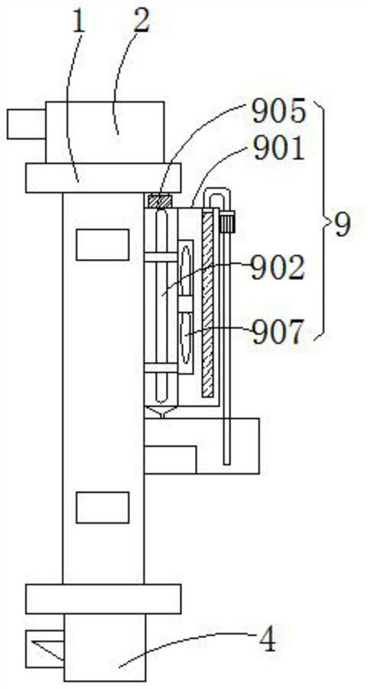
[0031] Such as Figure 1-5 As shown, a diesel engine radiator includes a frame 1, an upper water chamber 2, a cooling pipe 3 and a lower water chamber 4, the upper water chamber 2 is located at the upper end of the frame 1, and the upper side wall of the upper water chamber 2 is provided with The water inlet pipe 5 and the heat dissipation pipe 3 are located between the upper and lower racks 1, the lower water chamber 4 is fixedly installed at the lower end of the lower frame 1, and the side wall of the lower water chamber 4 is equipped with a water outlet pipe 6, and each adjacent two Radiating fins 7 are installed between the radiating pipes 3, cooling fans 8 are installed on the cooling fins 7, fixed plates 10 are installed on the left and right sides between the two racks 1 up and down, and the left and right two fixed plates 10 connect all the cooling pipes 3 sandwiched in the middle, the fixed pad 11 is fixedly installed on the fixed plate 10;

[0032]A temperature sens...


PUM


Abstract

The invention provides a diesel engine radiator, which relates to the field of engine heat dissipation devices, and includes a frame, an upper water chamber, a heat dissipation pipe and a lower water chamber. Radiating fins are installed between every two adjacent heat dissipation pipes, and cooling fins are installed on the cooling fins. A fan; a temperature sensor is installed inside the lower water chamber, and a cooling assembly is installed at the rear of the heat pipe close to the upper water chamber. The cooling assembly includes a fixed frame, and a water guide pipe is installed inside the fixed frame. The water inlet and the water outlet, the water inlet and the water outlet are all connected to the upper water chamber, and a cooling fan is installed at the rear of the fixed frame. In the present invention, through the setting of the temperature sensor and the cooling component, when the temperature of the cooling liquid in the lower water chamber is high, the cooling component is activated to reduce the temperature of the cooling liquid in the lower water chamber and ensure the overall cooling effect. The whole invention has a simple structure and can significantly Improve the heat dissipation efficiency of the radiator, ensure the efficient and stable operation of the diesel engine, and have high practicability.

Description

technical field [0001] The invention relates to the field of engine cooling devices, in particular to a diesel engine radiator. Background technique [0002] The engine radiator relies on the water pump driven by the engine to force the coolant to circulate in various parts of the engine. The coolant absorbs the heat generated by the engine and dissipates it into the air. The radiator is the basic performance of the radiator. It is characterized by various temperatures and heat before and after the heat exchange between air and high-temperature fluid water. It is characterized by the temperature of the air and water at the inlet of the radiator, the entire heat dissipation area of ​​the radiator, the heat transfer rate, and the fluids (air, water, etc.) ) is determined by the temperature of the air after heat absorption, the temperature of water after heat release, and the heat release of water (heat absorption of air) when receiving heat. [0003] Existing diesel engine ra...

Claims


Application Information

Patent Timeline
Patent Type & Authority Patents(China)
IPC IPC(8): F28D7/08F01P11/00F01P11/16F01P5/02
CPCF01P5/02F01P11/00F01P11/16F28D7/085
Inventor 姚国富陶再田何叶兵
Owner QUANJIAO SAIDELI MACHINERY
Learn More