A carbon dioxide gas cracking rock rod drilling equipment

A technology of carbon dioxide and rock cracking, applied in the direction of offensive equipment, earthwork drilling, blasting barrels, etc., can solve the problems of long consumption and low efficiency, and achieve the effect of saving time

Active Publication Date: 2022-06-24
昌吉雪峰爆破工程有限公司
View PDF12 Cites 0 Cited by
  • Summary
  • Abstract
  • Description
  • Claims
  • Application Information

AI Technical Summary

Problems solved by technology

[0005] In order to overcome the shortcoming that when there are many rock-cracking rods that need to be set, the staff need to spend a long time to complete the work and the efficiency is low. Therefore, the technical problem of the present invention is: to provide a carbon dioxide that can save time and improve work efficiency. Gas cracking rock rod drilling equipment

Method used


Image

  • A carbon dioxide gas cracking rock rod drilling equipment
  • A carbon dioxide gas cracking rock rod drilling equipment
  • A carbon dioxide gas cracking rock rod drilling equipment

Examples


Embodiment 1

[0028] A carbon dioxide gas cracking rod into the hole equipment, such as Figure 1-3 As shown, it includes a fixed pipe 1, a lower casing 2, a locking assembly 3 and a deceleration mechanism 4. The bottom of the fixed pipe 1 is fixed with a lower casing 2, and a locking assembly 3 is arranged in the lower casing 2. The locking assembly 3 is used for The rock splitting rod is locked, the fixed pipe 1 is provided with a deceleration mechanism 4, and the deceleration mechanism 4 is used to reduce the moving speed of the rock splitting rod.

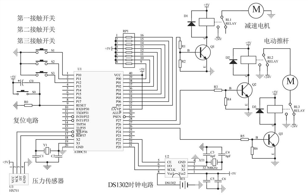
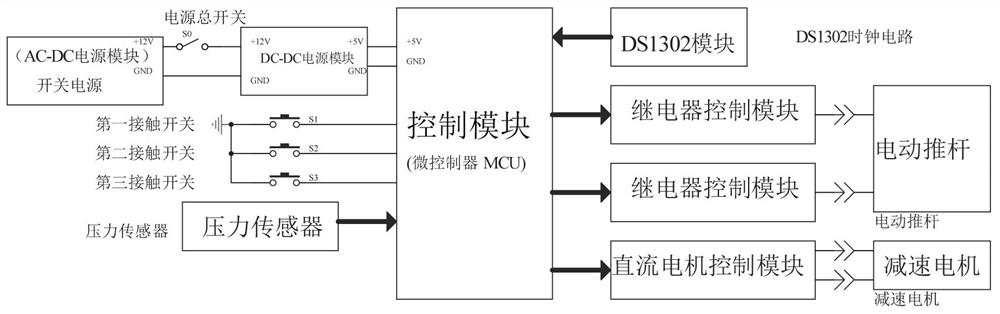
[0029] It also includes a control module, and both the locking assembly 3 and the deceleration mechanism 4 are wired to the control module.

[0030] The staff presses the main power switch, powers on the equipment, and then inserts the rock splitting rod into the lower casing 2. The rock splitting rod is pushed to the locking assembly 3, and the locking assembly 3 locks the rock splitting rod. The locking assembly 3 can also be used. Drive ...

Embodiment 2

[0032] On the basis of Example 1, as image 3 As shown, the locking assembly 3 includes an electric push rod 31 , a locking rod 32 , a first contact switch 33 , a second contact switch 34 and a pressure sensor 35 , and the electric push rod 31 , the first contact switch 33 are installed in the lower casing 2 And the pressure sensor 35, the first contact switch 33 is located between the electric push rod 31 and the pressure sensor 35, the push rod of the electric push rod 31 is fixed with a lock rod 32, and the left side of the lower housing 2 is installed with a second contact switch 34. The locking rod 32 is aligned with the second contact switch 34, the electric push rod 31 is connected with the control module through a peripheral circuit, and the first contact switch 33, the second contact switch 34 and the pressure sensor 35 are all wired to the control module.

[0033] When the equipment is powered on, the control module controls the pressure sensor 35 to work, the worker...

Embodiment 3

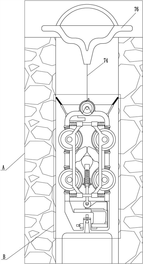
[0037] On the basis of Example 2, as Figure 2-6 As shown, a recovery assembly 7 is also included. The recovery assembly 7 includes a deceleration motor 71, a reel 72, a protection plate 73, a pull rope 74, a third contact switch 75 and a clamping ring 76. The top of the fixed tube 1 is installed with a deceleration The motor 71 and the protection plate 73, the deceleration motor 71 is located in the protection plate 73, the output shaft of the deceleration motor 71 is installed with a winding wheel 72, the winding wheel 72 is wound with a pull rope 74, and the pull rope 74 passes through the protection plate 73, A clamping ring 76 is connected to the pulling rope 74, a third contact switch 75 is arranged on the protection plate 73, the deceleration motor 71 is connected with the control module through a peripheral circuit, and the third contact switch 75 is connected with the control module by a circuit.

[0038] The worker puts the device into the pre-opened hole, puts the c...


PUM


Abstract

The invention relates to a hole-entry device, in particular to a carbon dioxide gas cracking rock rod hole-entry device. The technical problem of the present invention is how to provide a carbon dioxide gas cracking rock rod drilling equipment that can save time and improve work efficiency. A carbon dioxide gas rock-cracking rod entry device includes a fixed pipe, a lower casing, a locking assembly, etc.; live. The invention can reduce the speed of the rock-cracking rod moving downward through the deceleration mechanism, so that the staff can loosen the rock-cracking rod, and then set the rock-cracking rod in other areas, thereby saving time, and the device can be driven upward by the recovery component. Therefore, it is convenient for the staff to take out the device, and the gravel protection component can prevent the rubble from being stuck on the friction roller, making it difficult for the staff to take out the device.

Description

technical field [0001] The invention relates to a device for entering a hole, in particular to a device for entering a hole with a carbon dioxide gas rock splitting rod. Background technique [0002] Rock split rod is a blasting tool, which is widely used in mining and construction fields. Compared with the previous blasting methods, the blasting operation through rock split rod is relatively simple, with low cost and high safety. You need to pre-cut a hole in the rock, and then put the crack rod into the hole. [0003] At present, the staff usually puts the split rock rod into the pre-opened hole manually. In order to avoid damage to the split rock rod, the staff needs to slowly put the split rock rod into the hole, and cannot directly loosen the split rock rod. The rock splitting rods fall to the bottom of the cave under their own gravity, and when there are many rock splitting rods to be set, it takes a long time for the staff to complete the work, and the efficiency is ...

Claims


Application Information

Patent Timeline
Patent Type & Authority Patents(China)
IPC IPC(8): F42D1/00F42D3/04F42B3/04E21C37/14
CPCF42D1/00F42D3/04F42B3/04E21C37/14
Inventor 余天哲
Owner 昌吉雪峰爆破工程有限公司
Why Eureka
Try Eureka