High-voltage output converter

A high-voltage output and converter technology, applied in the field of high-voltage output converters, can solve the problem of unsolved leakage inductance energy and other problems, and achieve the effects of reducing switching loss, power consumption, and reverse current.

Inactive Publication Date: 2020-04-17
MORNSUN GUANGZHOU SCI & TECH
View PDF6 Cites 2 Cited by
  • Summary
  • Abstract
  • Description
  • Claims
  • Application Information

AI Technical Summary

Problems solved by technology

This scheme adopts two working processes of forward and flyback. Compared with the single flyback scheme, this scheme increases the forward working process and improves the work efficiency to a certain extent, but it still does not solve the problem of leakage inductance energy and The problem with ZVS

Method used


Image

  • High-voltage output converter
  • High-voltage output converter
  • High-voltage output converter

Examples


no. 1 example

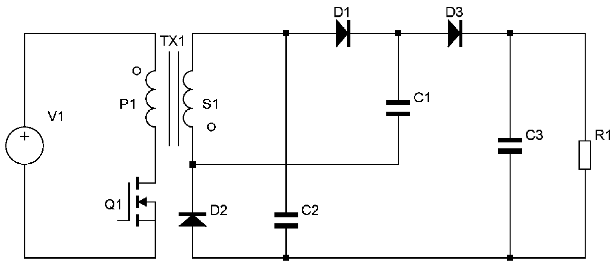
[0021] figure 2 It is a schematic diagram of the first embodiment of the switching converter power stage of the high-voltage output converter of the present invention, and the connection relationship of this embodiment is as follows:

[0022] The input positive terminal is electrically connected to the terminal with the same name of the primary winding P1 of the transformer TX1, the terminal with the same name of the primary winding P1 of the transformer TX1 is electrically connected to the drain of the MOS transistor Q1, the source of the MOS transistor Q1 is electrically connected to the input negative terminal, and the MOS The drain of the tube Q1 is also electrically connected to the source of the MOS tube Q2, the drain of the MOS tube Q2 is electrically connected to the positive terminal of the capacitor C4, the negative terminal of the capacitor C4 is electrically connected to the positive input terminal, and the secondary winding S1 of the transformer TX1 The opposite ...

no. 2 example

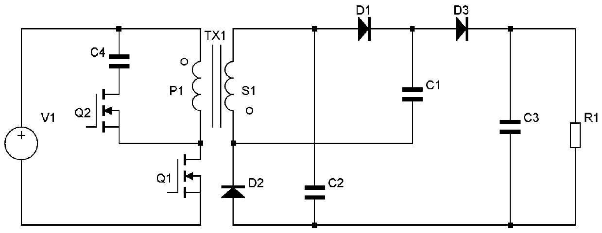
[0035] Figure 5 It is a schematic circuit diagram of a high-voltage output converter according to the second embodiment of the present invention. Wherein, compared with the first embodiment, the clamping circuit composed of MOS transistors and capacitors is not connected to the primary winding of the transformer, but is connected to the auxiliary winding. Since the clamp tube is connected to the auxiliary winding, its source voltage can be fixed, no bootstrap drive circuit is needed, and a conventional circuit (such as a totem pole circuit) can be used for driving, simplifying the drive circuit.

[0036] The connection relationship of this embodiment is as follows:

[0037] The input positive terminal is electrically connected to the same-named terminal of the primary winding P1 of the transformer TX1, the different-named terminal of the primary winding P1 of the transformer TX1 is electrically connected to the drain of the MOS transistor Q1, and the source of the MOS transi...


PUM


Abstract

The invention provides a high-voltage output converter which uses a positive flyback circuit and comprises an input positive end, an input negative end, a transformer TX1, an MOS transistor Q1, an MOStransistor Q2, a diode D1, a diode D2, a diode D3, a capacitor C1, a capacitor C2, a capacitor C3, a capacitor C4, an output positive end and an output negative end. According to the connection relation, the input positive end, the dotted terminal of the primary winding of the transformer TX1, the drain electrode of the MOS transistor Q1 and the input negative end are connected in sequence; the capacitor C2 and the MOS transistor Q2 are connected in series and then are connected in parallel to two ends of the primary winding; the synonym end of the secondary winding of the transformer TX1, the diodes D1 and D3 and the output positive end are connected in series; the output negative end, the diode D2 and the dotted terminal of the secondary winding of the transformer TX1 are sequentially connected in series; the capacitor C1 is connected in parallel between the cathode of the diode D1 and the dotted terminal of the secondary winding of the transformer TX1, the capacitor C2 is connectedin parallel between the synonym terminal of the secondary winding of the transformer TX1 and the anode of the diode D2, and the capacitor C3 is connected in parallel between the output positive terminal and the output negative terminal. High-voltage output can be realized, and main power is ensured to realize ZVS in a full-load range.

Description

technical field [0001] The invention relates to a converter circuit, in particular to a high-voltage output converter. Background technique [0002] In the field of switching power supply applications, high-voltage output power supplies are required in many occasions: during high-voltage direct current transmission, the power supply terminal needs to increase the voltage; in medical X-ray machines, the ray tube needs to work under high-voltage electric fields; in industrial electrostatic dust removal applications In the process, a high-voltage direct current needs to be applied between the discharge electrode and the dust-collecting electrode... If the basic topology of the flyback is used in the field of high-voltage output, the voltage can be increased by multi-winding or multi-stage voltage doubler rectification by capacitors and diodes. To achieve the purpose of high output voltage, but the above methods have certain limitations. [0003] The method of multi-winding rec...

Claims


Application Information

Patent Timeline
Patent Type & Authority Applications(China)
IPC IPC(8): H02M3/335
CPCH02M3/33569H02M1/0058Y02B70/10
Inventor 尹向阳刘晓旭王志燊
Owner MORNSUN GUANGZHOU SCI & TECH
Why Eureka
Try Eureka