
Control method of bidirectional LLC circuit of power converter

A technology of a power converter and a control method, applied in the direction of converting DC power input to DC power output, output power conversion device, control/regulation system, etc., can solve the problems of transmission gain limitation, difficult gain range, etc. The effect of gain range

Active Publication Date: 2020-04-17
深圳市能效电气技术有限公司
View PDF6 Cites 4 Cited by
  • Summary
  • Abstract
  • Description
  • Claims
  • Application Information

AI Technical Summary

Problems solved by technology

However, in a bidirectional converter, if the transformer turns ratio is kept at 1, the maximum forward and reverse gain provided by the converter by adjusting the switching frequency is also around 1.1, and it is difficult to achieve a wider gain range
Moreover, the traditional LLC circuit works in the reverse direction, the excitation inductance is clamped by the reverse input voltage and does not participate in the resonance work. In the case of the LC resonance mode, the LC resonant cavity and the output end form a series voltage divider relationship.
The impedance of the LC resonant cavity changes with the switching frequency. When the switching frequency is the resonant frequency, the impedance of the LC resonant cavity is the smallest, and the frequency gain is at most 1, which limits the transmission gain.

Method used


Image

  • Control method of bidirectional LLC circuit of power converter
  • Control method of bidirectional LLC circuit of power converter
  • Control method of bidirectional LLC circuit of power converter

Examples


Embodiment Construction

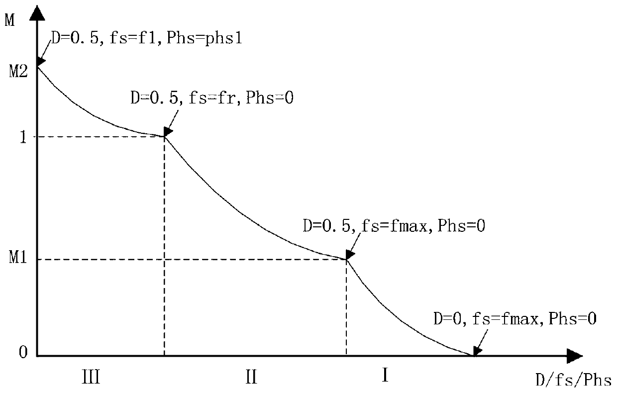
[0023] In the LLC topology circuit, limited by the loss condition of the switching device, it is necessary to set the highest operating switching frequency. When the switching frequency is high, its frequency is already insensitive to gain adjustment. Therefore, when the positive and negative working frequency of the LLC circuit is between the resonant frequency and the highest switching frequency, its gain is monotonic. In this working range, the switching duty cycle of the input side can be fixed at 50%, and the transmission gain can be adjusted by adjusting the switching frequency of the input side.

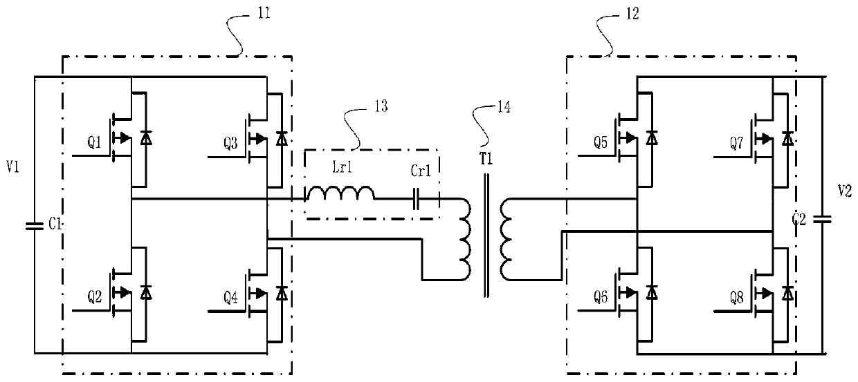
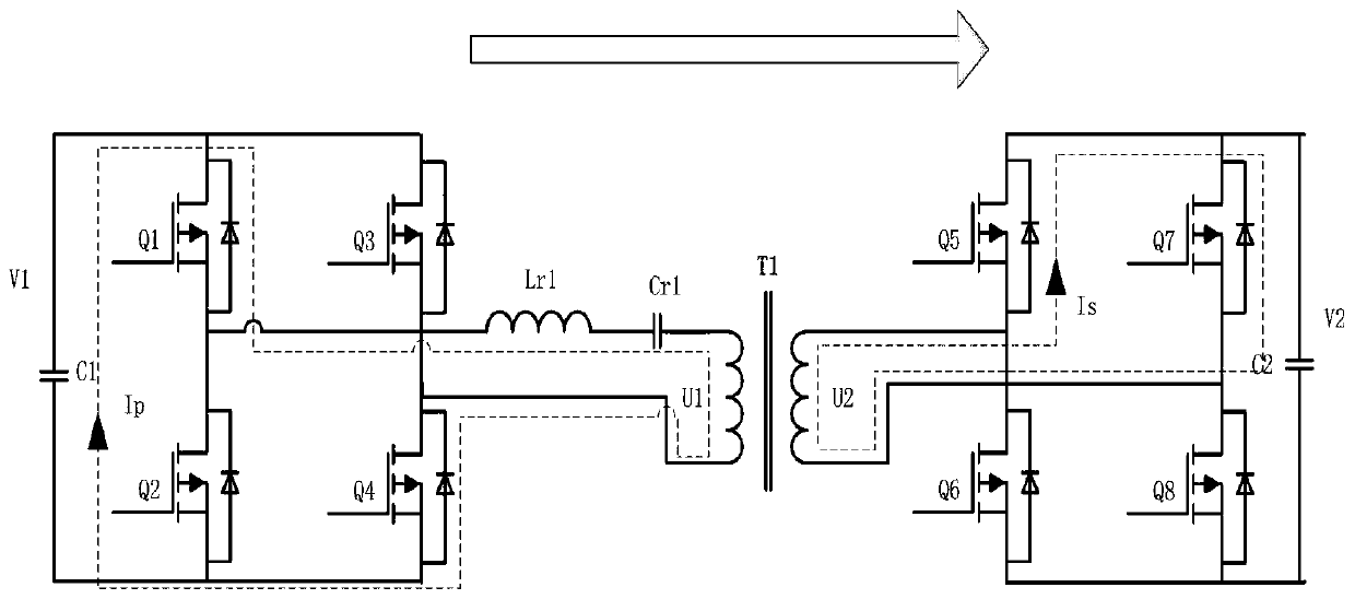
[0024] Therefore, the present invention proposes a control method for expanding the gain range of a bidirectional LLC circuit of a power converter. When working in forward and reverse directions, the switching tube on the input side of the converter works in a fixed switching frequency and 50% switching duty cycle mode, and the switching tube on the rectifying side of the con...


PUM


Abstract

The invention discloses a control method of a bidirectional LLC circuit of a power converter. The bidirectional LLC circuit comprises a first H-bridge circuit, a second H-bridge circuit and a transformer, and the first H-bridge circuit and the second H-bridge circuit are respectively connected to windings at two sides of the transformer; when the bidirectional LLC circuit works in a forward direction, the first H-bridge circuit is the input side, and the second H-bridge circuit is the rectification side. When the bidirectional LLC circuit works in a reverse direction, the second H-bridge circuit is the input side, and the first H-bridge circuit is the rectification side. The control method comprises adjustment in a transmission gain range of greater than 1, a switching tube on the input side works in a mode of fixed switching frequency and a fixed switching duty ratio of 50%, switching tubes of two half-bridges on the rectification side work in a phase shift control mode, alternate Boost voltage increase is realized, and the Boost voltage increase ratio is adjusted by adjusting a phase shift value, so that the gain of the bidirectional LLC circuit is greater than 1. According to the invention, the bidirectional converter can work in a relatively wide gain range in a bidirectional manner through a software modulation method without independently adding devices.

Description

[technical field] [0001] The invention relates to a bidirectional LLC circuit of a power converter, in particular to a control method for a bidirectional LLC circuit of a power converter. [Background technique] [0002] The bidirectional power converter can flow the DC energy of the electric vehicle with the AC grid in both directions, can interact the DC energy of the electric vehicle with the microgrid in both directions, can flow the DC energy of the electric vehicle with the energy storage station in both directions, and can also invert the DC energy of the electric vehicle Powering household appliances. [0003] The composition of the bidirectional LLC circuit of prior art is as figure 1 shown. The LLC circuit includes two H-bridge circuits 11 , an H-bridge circuit 12 and a high-frequency transformer 14 each composed of four MOS tubes. The DC side voltage of the H-bridge circuit 11 is V1, and the H-bridge circuit 11 is connected to one side winding of the high-freque...

Claims


Application Information

Patent Timeline
Patent Type & Authority Applications(China)
IPC IPC(8): H02M3/335
CPCH02M3/33584H02M3/33592Y02B70/10Y02T10/7072Y02T10/70
Inventor 周强阮世良吴景童
Owner 深圳市能效电气技术有限公司
Learn More