Anti-hysteresis method and device for piezoelectric ceramic, equipment and medium

A piezoelectric ceramic and hysteresis technology, applied in the field of slope-based linear equation anti-hysteresis, can solve problems such as difficult applications, and achieve the effects of improving positioning and control accuracy, high implementability and operability

Active Publication Date: 2020-04-17
HUAQIAO UNIVERSITY
View PDF1 Cites 2 Cited by
  • Summary
  • Abstract
  • Description
  • Claims
  • Application Information

AI Technical Summary

Problems solved by technology

To sum up, at present, most scholars use complex modeling control algorithms to correct the hysteresis nonlinearity of piezoelectric ceramics, but it is difficult to apply it in actual control. Therefore, in order to overcome the positioning accuracy error caused by hysteresis characteristics, it is necessary to study a Therefore, it is necessary to study a slope-based linear equation anti-hysteresis method to realize the correction of piezoelectric ceramic hysteresis nonlinearity.

Method used


Image

  • Anti-hysteresis method and device for piezoelectric ceramic, equipment and medium
  • Anti-hysteresis method and device for piezoelectric ceramic, equipment and medium
  • Anti-hysteresis method and device for piezoelectric ceramic, equipment and medium

Examples


Embodiment 1

[0037] This embodiment provides an anti-hysteresis method for piezoelectric ceramics, such as figure 2 shown, including the following steps:

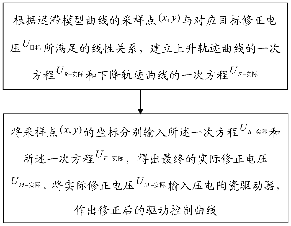
[0038] S1. According to the sampling point (x, y) of the hysteresis model curve and the corresponding target correction voltage U 目标 Satisfied linear relationship, establish the first-order equation U of the rising trajectory curve R-实际 and the linear equation U of the descending trajectory curve F-实际 ;Such as Figure 2a As shown, specifically include the direct steps:

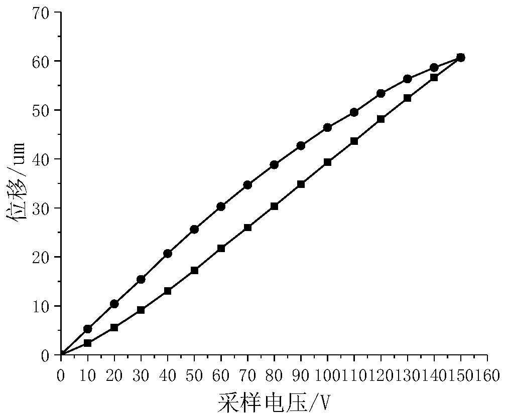
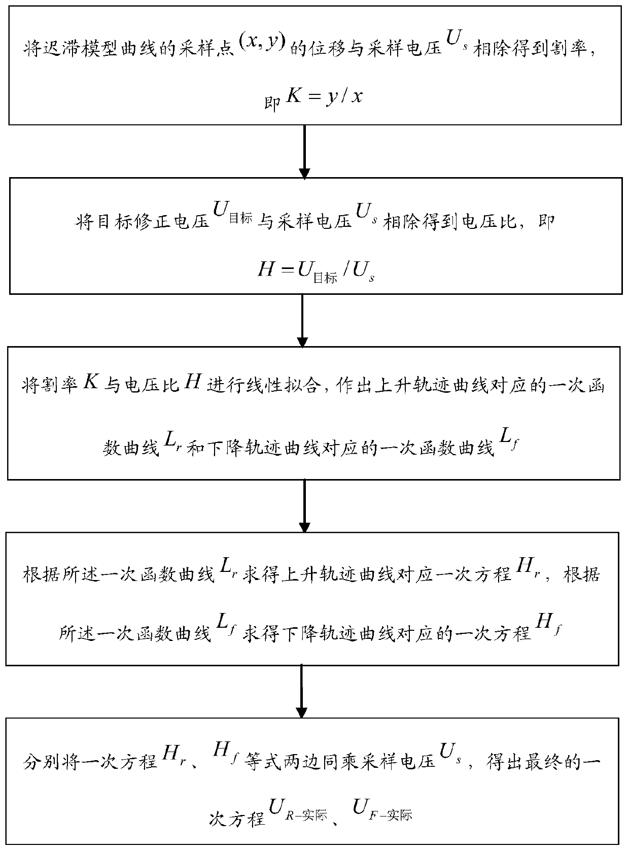
[0039] S11, the displacement F of the sampling point (x, y) of the hysteresis model curve s and sampling voltage U s Divide to get the cut rate, that is, K=y / x=F s / U s ;Such as Figure 2b As shown, the calculation process of cut rate is as follows:

[0040](1) Connect the first and last two points of the hysteresis model curve to make a corrected straight line;

[0041] (2) Find the hysteresis nonlinear law curves of the rising trajectory and the falling tra...

Embodiment 2

[0068] In this embodiment, a piezoelectric ceramic anti-hysteresis device is provided, such as Figure 10 shown, including:

[0069] The equation building module is used to correct the voltage U according to the sampling point (x, y) of the hysteresis model curve and the corresponding target 目标 Satisfied linear relationship, establish the first-order equation U of the rising trajectory curve R-实际 and the linear equation U of the descending trajectory curve F-实际 ;

[0070] A correction module for inputting the coordinates of the sampling points (x, y) into the primary equation U respectively R-实际 and the linear equation U F-实际 , to obtain the final actual correction voltage U M-实际 , will actually correct the voltage U M-实际 Input the piezoelectric ceramic drive and make the corrected drive control curve.

[0071] Wherein, the equation building module specifically includes:

[0072] The cutting rate calculation module is used to convert the displacement F of the sampling ...

Embodiment 3

[0085] This embodiment provides an electronic device, such as Figure 11 As shown, it includes a memory, a processor, and a computer program stored in the memory and operable on the processor. When the processor executes the computer program, any implementation manner in Embodiment 1 can be realized.

[0086] Since the electronic device introduced in this embodiment is the device used to implement the method in Embodiment 1 of this application, based on the method described in Embodiment 1 of this application, those skilled in the art can understand the electronic device of this embodiment. Specific implementation methods and various variations thereof, so how the electronic device implements the method in the embodiment of the present application will not be described in detail here. As long as a person skilled in the art implements the equipment used by the method in the embodiment of the present application, it all belongs to the protection scope of the present application....


PUM


Abstract

The invention provides an anti-hysteresis method and device for piezoelectric ceramics, equipment and a medium, and the method comprises the steps: S1, building a linear equation UR-shiji of a risingtrack curve and a linear equation UF-shiji of a falling track curve according to the linear relation between a sampling point (x, y) of a hysteresis model curve and a corresponding target correction voltage U target; and S2, finally, respectively inputting the coordinates of the sampling point (x, y) into the linear equation UR-shiji of the rising track curve and the linear equation UF-shiji of the falling track curve to obtain a final actual correction voltage UM-shiji, and actually inputting the actual correction voltage UM-shiji into a piezoelectric ceramic driver to draw a corrected driving control curve. Through the two linear equations, the anti-hysteresis method and device are higher in feasibility and operability, and provide a scientific reference basis for the further improvementof the positioning and control precision of the piezoelectric ceramic driver.

Description

technical field [0001] The invention relates to the technical field of anti-hysteresis of piezoelectric ceramics, in particular to a linear equation anti-hysteresis method, device, equipment and medium based on slope of piezoelectric ceramics hysteresis nonlinearity. Background technique [0002] As the main driving element of the micro-displacement mechanism, the piezoelectric ceramic driver has the advantages of good stability, fast response, high displacement resolution, easy installation, and high precision. New functional smart materials that convert electrical energy into micro-displacements are widely used in micro-positioning platforms, precision machining, microelectronics, biomedicine and other fields. [0003] Piezoelectric ceramics have hysteresis characteristics, nonlinearity and creep characteristics. Among them, the hysteresis characteristics of piezoelectric ceramics refer to the difference between the step-up and step-down displacement curves of the same pie...

Claims


Application Information

Patent Timeline
Patent Type & Authority Applications(China)
IPC IPC(8): H02N2/00H02N2/06
CPCH02N2/0075H02N2/062
Inventor 范伟傅雨晨金花雪王寅占炜杨建红
Owner HUAQIAO UNIVERSITY
Why Eureka
Try Eureka