
Prediction compensation method for back-up roller eccentricity of cold-rolling mill
A compensation method and a technology for supporting rolls, which are applied in the direction of rolling mill control devices, metal rolling, metal rolling, etc., can solve problems such as errors, inaccurate calculation of phase angle for eccentric compensation, and inconvenient installation and maintenance.
- Summary
- Abstract
- Description
- Claims
- Application Information
AI Technical Summary
Problems solved by technology
Method used
Image

Examples
Embodiment Construction
[0076] The present invention will be further described below in conjunction with specific examples and accompanying drawings.
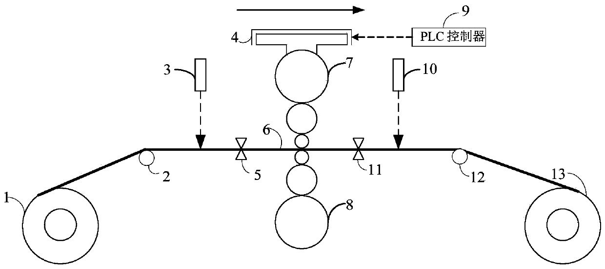
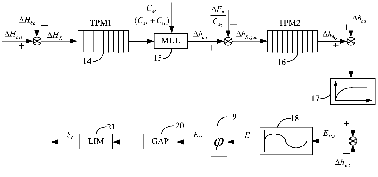
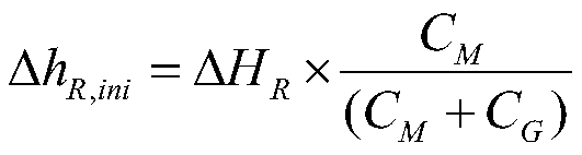
[0077] The thickness control system of a single-stand six-high reversing cold rolling mill is as follows: figure 1 As shown in the figure, the current rolling direction is from left to right, and the next pass will be from right to left, and then reverse the rolling repeatedly. In the current pass, the strip steel 6 is started from the entrance coiler 1, passed through the diverting roll 2 and then rolled in a six-high rolling mill, where 7 and 8 are the upper and lower support rolls of the rolling mill, and the hydraulic cylinder 4 provides rolling Force, then through the steering roller 12, finally coiled on the exit coiler 13. The unit is equipped with first and second laser speed gauges 3 and 10, which are respectively used to measure the speed at the entrance and exit of the rolling mill, and is also equipped with first and second thickness gaug...
PUM
 Abstract
Description
Claims
Application Information