Shifting fork plane machining equipment

A plane and equipment technology, applied in the field of shift fork plane workbench equipment, can solve the problems of low machining accuracy, troublesome and low production efficiency of parts, and achieve the effects of improving work efficiency, convenient operation and shortening work steps.

Active Publication Date: 2020-04-21
贵州友擘机械制造有限公司
View PDF9 Cites 0 Cited by
  • Summary
  • Abstract
  • Description
  • Claims
  • Application Information

AI Technical Summary

Problems solved by technology

Since the upper and lower planes of the reverse gear fork have to be milled, two clamping and alignment are required, which is very troublesome, resulting in low machining accuracy and low production efficiency.

Method used


Image

  • Shifting fork plane machining equipment
  • Shifting fork plane machining equipment
  • Shifting fork plane machining equipment

Examples


Embodiment 1

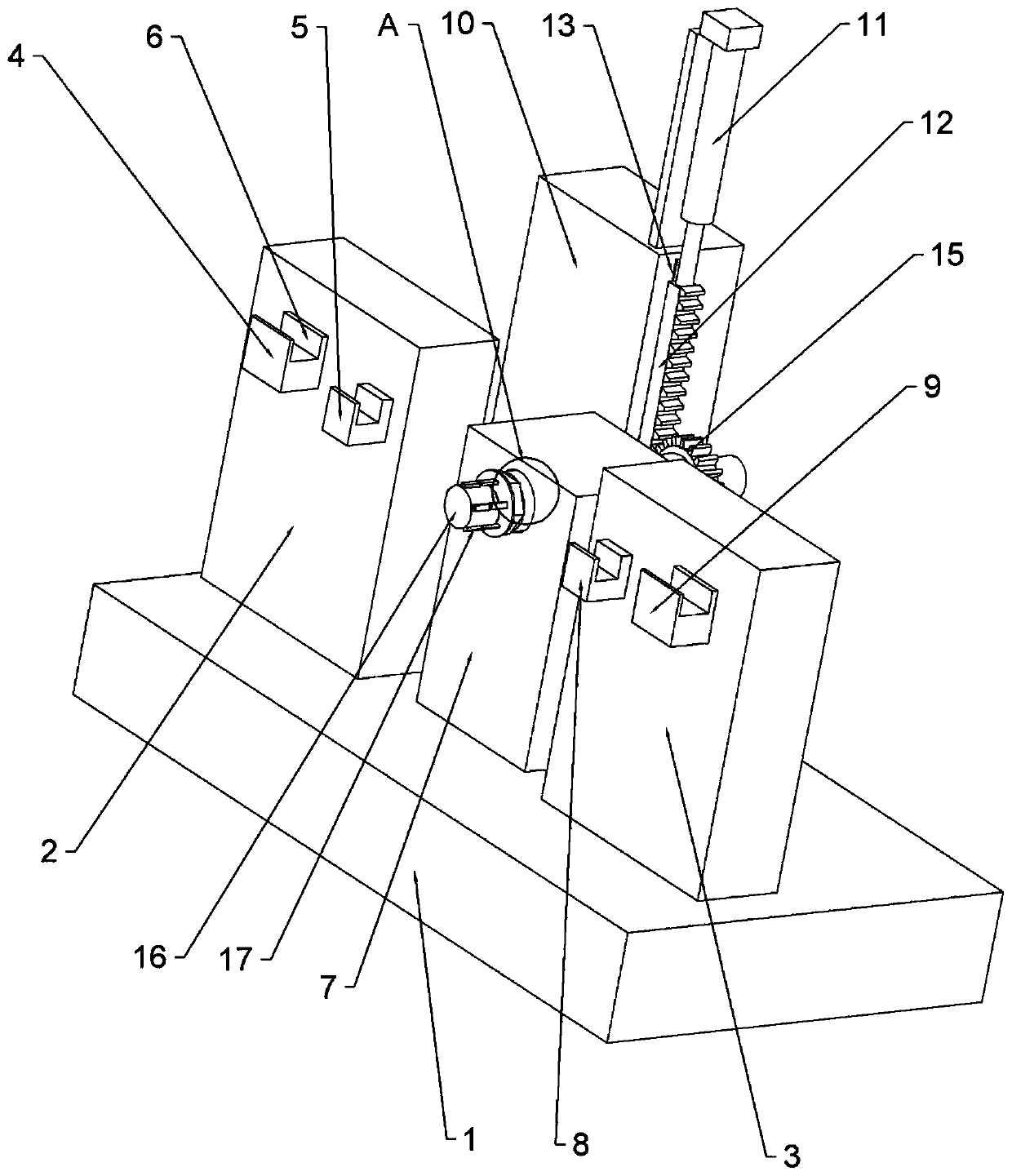
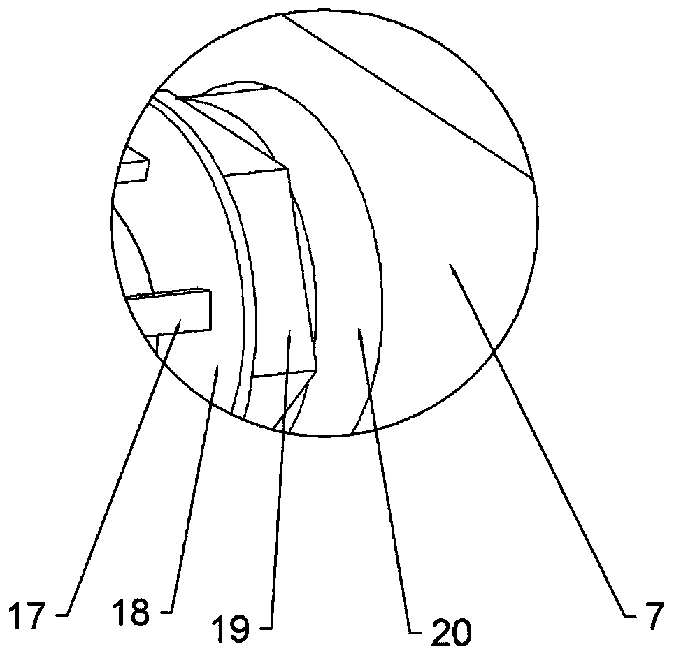
[0025] This embodiment is basically as attached Figure 1-Figure 4 Shown: a fork plane machining equipment, including a workbench 1 and a milling machine (not shown). The milling machine is a milling machine in the prior art, and its structure and usage are known to those skilled in the art, and will not be described in detail here. The upper end surface of the workbench 1 is provided with the first vertical plate 2, the fixed plate 7 and the second vertical plate 3 in sequence, and the connection mode between the first vertical plate 2, the second vertical plate 3 and the fixed plate 7 and the workbench 1 can be clamping , welded or connected by screws, etc. The end of the first vertical plate 2 is provided with a first support portion for supporting the lower end surface of the shift fork; the first support portion includes a first support block 5 and a first positioning block 4 . Both the first supporting block 5 and the first positioning block 4 are fixed on the end surf...

Embodiment 2

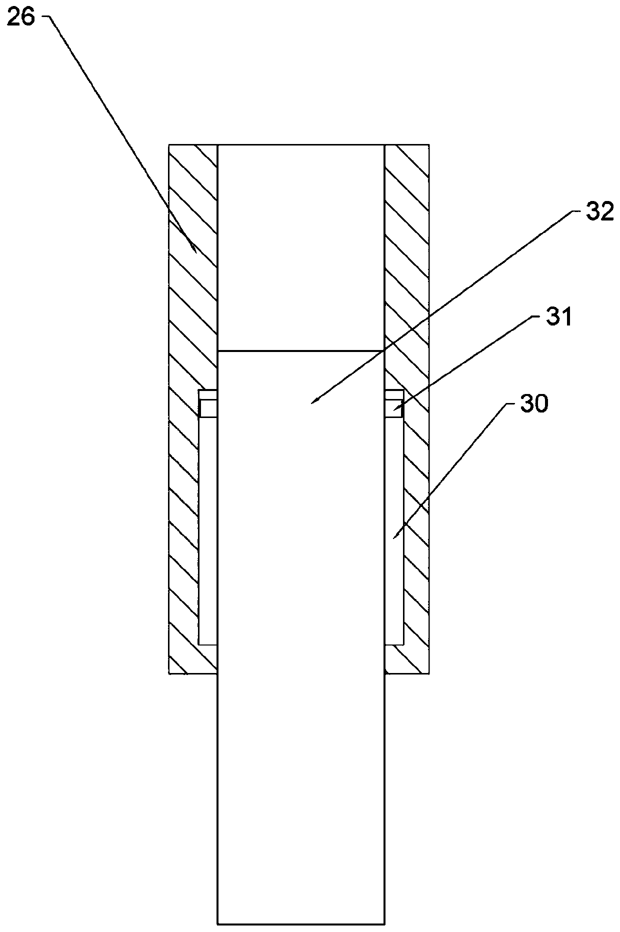
[0033] Such as Figure 5 As shown, the difference between this embodiment and Embodiment 1 is that this embodiment also includes a limiting plate 25, which is fixedly connected to the bracket 10, and the connection method can be welding or clamping. A through hole is opened in the middle of the limiting plate 25, and the end of the fixing column 16 away from the fixing part passes through the through hole. The side wall of the part of the fixing column 16 positioned in the through hole has a groove 22, and the side wall of the through hole has a limit groove 30, and a limit pin 14 and a spring 23 are arranged in the limit groove 30, and the two ends of the spring 23 are respectively connected with the limit groove. The bottom wall of the groove 30 and the end of the limit pin 14 are connected by screws. The left end of the limit pin 14 is hemispherical and the left end of the limit pin 14 can extend into the groove 22 .

[0034] Under natural circumstances, the left end of t...

Embodiment 3

[0036] Such as Figure 6 As shown, the difference between this embodiment and the second embodiment is that this embodiment also includes an air blowing structure for blowing air to the shift fork. The air blowing structure comprises an elastic bellows 21 (also can be a foot pump), and the lower end of the elastic bellows 21 is bonded to the upper end of the workbench 1 . The elastic bellows 21 is connected with an air blowing pipe (not shown in the figure), and the air outlet end of the air blowing pipe faces the first supporting part. The present embodiment also includes a one-way air inlet valve and a one-way air outlet valve (not shown in the figure), the elastic bellows 21 has an air inlet, and the one-way air inlet valve is arranged at the air inlet of the elastic bellows 21 . The one-way air outlet valve is arranged at the joint between the elastic bellows 21 and the air blowing pipe. Both the one-way inlet valve and the one-way outlet valve are prior art, and their s...


PUM


Abstract

The invention belongs to the field of machining equipment and particularly discloses shifting fork plane machining equipment. The equipment comprises a workbench and a milling machine, wherein a firstvertical plate, a fixing plate and a second vertical plate are sequentially arranged on an end face of the workbench, a first supporting part used for supporting a lower end face of a shifting fork is arranged at an end of the first vertical plate, a second supporting part for supporting an upper end face of the shifting fork is arranged on an end face of the second vertical plate, a fixing column is arranged on the end face of the fixing plate, a fixing part capable of fixing the shifting fork is arranged in the circumferential direction of the fixing column, the fixing column is rotationally connected with the fixing plate, and a driving structure for driving the fixing column to rotate is further arranged on the workbench. The equipment is advantaged in that the upper end face and thelower end face of the shifting fork can be automatically machined, and working efficiency is improved.

Description

technical field [0001] The application of the present invention relates to the field of mechanical processing equipment, in particular to a fork plane workbench equipment. Background technique [0002] The shift fork is a part of the car gearbox, which is connected to the shift handle and located at the lower end of the handle. The middle shift wheel is moved to change the input / output speed ratio. The shift fork is mainly used for clutch shifting. The reverse gear fork is one of the important parts of the automobile transmission. It is a cast-shaped part, and the upper and lower planes of the reverse gear fork need to be finished with a milling machine. The shaft part is clamped, and then processed by a horizontal milling machine. Since the upper and lower planes of the reverse gear fork are milled, two clamping and alignment are required, which is very troublesome, resulting in low machining accuracy and low production efficiency. Contents of the invention [0003] Th...

Claims


Application Information

Patent Timeline
IPC IPC(8): B23C3/00B23Q3/06B23Q11/00
CPCB23C3/00B23Q3/062B23Q11/005
Inventor 陈明友
Owner 贵州友擘机械制造有限公司
Why Eureka
Try Eureka