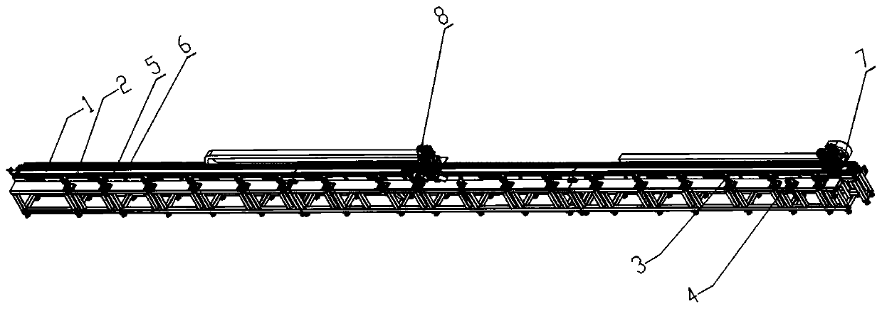
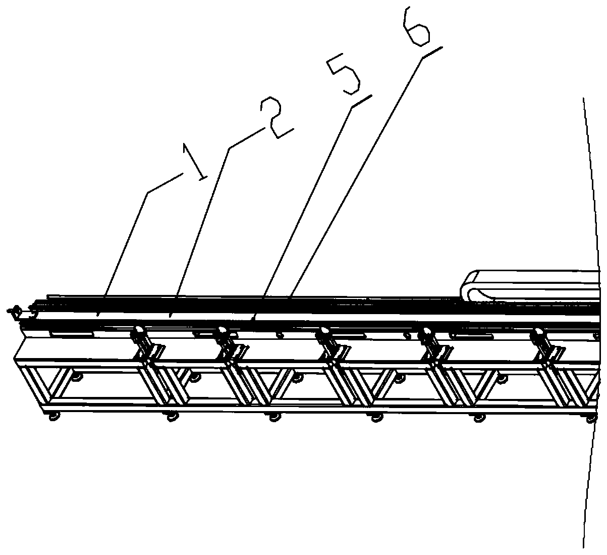
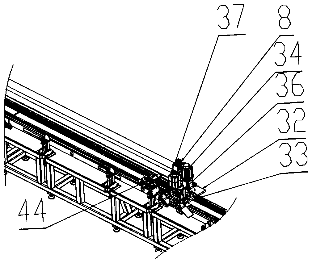
Full-automatic pipe cutting machine
A pipe cutting machine, fully automatic technology, applied in the direction of metal sawing equipment, sawing machine, metal processing equipment, etc., can solve the problem of difficult cutting of large pipe fittings, and achieve the effect of shortening time, ingenious design, and simple structure
- Summary
- Abstract
- Description
- Claims
- Application Information
AI Technical Summary
Problems solved by technology
Method used
Image

Examples
Embodiment Construction
[0032] It should be noted that, in the case of no conflict, the embodiments in the present application and the features in the embodiments can be combined with each other.
[0033] In the description of the present application, it should be understood that the terms "center", "longitudinal", "transverse", "upper", "lower", "front", "rear", "left", "right", " The orientation or positional relationship indicated by "vertical", "horizontal", "top", "bottom", "inner", "outer", etc. is based on the orientation or positional relationship shown in the drawings, and is only for the convenience of describing the present application and Simplified descriptions do not indicate or imply that the device or element referred to must have a specific orientation, be constructed and operate in a specific orientation, and thus should not be construed as limiting the scope of protection of the present application. In addition, the terms "first", "second", etc. are used for descriptive purposes on...
PUM
 Abstract
Description
Claims
Application Information
PatSnap Eureka turns technology decisions into work you can execute. Powered by our Innovation Knowledge Graph, it runs expert workflows across engineering, life sciences, materials and intellectual property. Get your review-ready output in minutes.


