Powder cleaning device of laser sintering equipment

A laser sintering and powder cleaning technology, used in manufacturing auxiliary devices, metal processing equipment, 3D object support structures, etc., can solve the problems of low powder cleaning efficiency, unfavorable powder recovery, lack of powder screening, etc., to achieve easy recovery. , the effect of easy reuse

Inactive Publication Date: 2020-04-21
安徽卓锐三维科技有限公司
View PDF4 Cites 3 Cited by
  • Summary
  • Abstract
  • Description
  • Claims
  • Application Information

AI Technical Summary

Problems solved by technology

[0004] After the sintering is completed, it is generally necessary to cool down first, and then clean the powder of the finished product in the powder bag. Use tools to roughly peel off the parts in the powder bag, and then spray the powder on the surface of the parts with compressed air. Some small places that cannot be processed need to be removed with iron wire or other tools. However, the current powder cleaning is generally done manually, and the efficiency of powder cleaning is low, which is not conducive to improving production efficiency. On the other hand, after powder cleaning is completed The lack of sieving of the powder in the end is not conducive to the recovery of part of the unsintered powder, resulting in a large waste

Method used


Image

  • Powder cleaning device of laser sintering equipment
  • Powder cleaning device of laser sintering equipment
  • Powder cleaning device of laser sintering equipment

Examples


Embodiment Construction

[0028] The following will clearly and completely describe the technical solutions in the embodiments of the present invention with reference to the accompanying drawings in the embodiments of the present invention. Obviously, the described embodiments are only some, not all, embodiments of the present invention. Based on the embodiments of the present invention, all other embodiments obtained by persons of ordinary skill in the art without making creative efforts belong to the protection scope of the present invention.

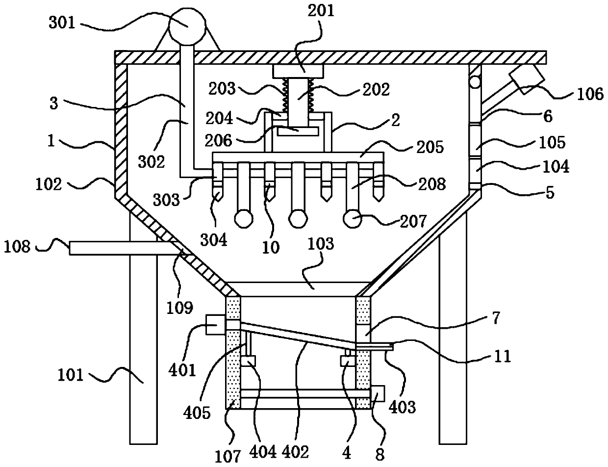
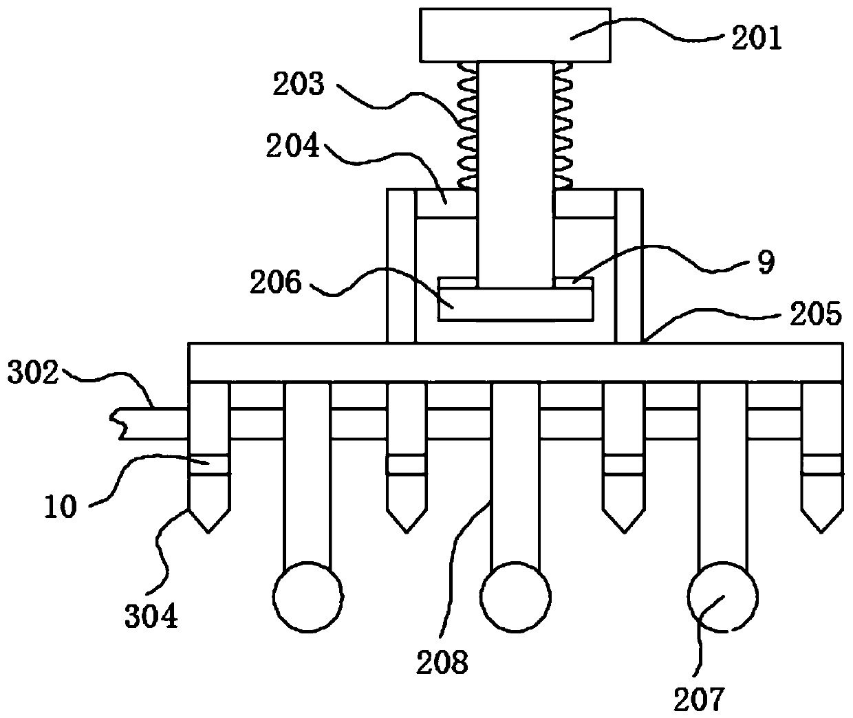
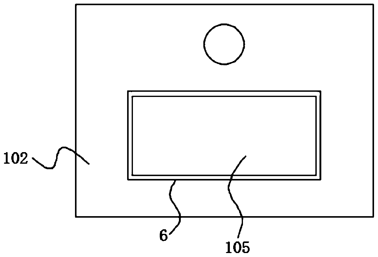
[0029] see Figure 1-4 , the present invention provides a technical solution: a powder cleaning device for laser sintering equipment, including: a powder cleaning box assembly 1, and the powder cleaning box assembly 1 includes a support frame 101, a box body 102, a grid plate 103, a door panel 104, and an observation window 105 and electric push rod 106, the box body 102 is fixed on the upper part of the support frame 101 by bolts, the door panel 104 is hinged...


PUM

PropertyMeasurementUnit
Apertureaaaaaaaaaa

Abstract

The invention discloses a powder cleaning device of laser sintering equipment. The powder cleaning device comprises a powder cleaning box assembly, a beating assembly, a blowing assembly and a vibrating screen assembly, wherein the powder cleaning box assembly comprises a supporting frame, a box body, a grid plate, a door plate, an observation window and an electric push rod; the beating assemblycomprises a connecting block, a guide rod, a compression spring, a sliding block, a connecting frame, an electromagnet and a beating hammer; the blowing assembly comprises a fan, a corrugated hose, anair guide pipe and a nozzle; and the vibrating screen assembly comprises a vibrating motor, a vibrating screen, a slag guide plate and a supporting block. According to the powder cleaning device, a powder cleaning space is formed through the powder cleaning box assembly, the surface side of a product to be subjected to powder cleaning is beaten through the beating assembly, and the preliminary powder cleaning process is achieved; blowing is conducted through the blowing assembly in the beating process, and fine powder particles are removed from the surface side of the product; and large-particle sundries and small-particle sundries generated by powder cleaning are screened through the vibrating screen assembly, and subsequent recycling is facilitated.

Description

technical field [0001] The invention relates to the technical field of laser sintering powder cleaning, in particular to a powder cleaning device for laser sintering equipment. Background technique [0002] Laser sintering, the technology of sintering powder compacts with laser as the heat source, has unique advantages for sintered materials that are difficult to complete in conventional sintering furnaces. The sintering of the product is easy to sinter the powder or flake compact that is different from the matrix composition. Compared with other rapid prototyping technologies, the parts prepared by laser sintering have the characteristics of good performance, fast production speed, diverse materials, and low cost. . [0003] Laser sintering is a layered manufacturing technology. The premise of this technology is that the three-dimensional data of the object is available, and then the three-dimensional description is converted into a set of slices. Each slice describes the ...

Claims


Application Information

Patent Timeline
IPC IPC(8): B29C64/153B29C64/35B29C64/357B29C64/379B33Y40/00B33Y40/20
CPCB33Y40/00B29C64/153B29C64/35B29C64/357B29C64/379
Inventor 黄华锋樊子均江姣龙廖彬
Owner 安徽卓锐三维科技有限公司
Why Eureka
Try Eureka