
Light lead screw lifting mechanism

A screw lift and screw technology, applied in the field of robots, can solve the problems of low resistance to external interference, high rigidity of the lifting bucket itself, low overall reliability, etc., and achieve the effects of light weight, small overall size, and large lifting stroke.

Inactive Publication Date: 2020-04-21
HEFEI CSG SMART ROBOT TECH CO LTD
View PDF18 Cites 0 Cited by
  • Summary
  • Abstract
  • Description
  • Claims
  • Application Information

AI Technical Summary

Problems solved by technology

Steel wire rope and belt transmission rely on their own gravity to drop, the overall rigidity is poor during the lifting process, the ability to resist external interference is low, and the overall reliability of the mechanism is low; the chain lifting depends on the stiffness generated by the 90° limit between the chains to transmit Movement, but due to the size factor of the chain itself, the size of the contraction is relatively large, which makes its use more limited; while most of the screw lifts on the market have only three to four stages, and the stability of the lifting process depends on each The interference fit between the buckets is guaranteed. On the one hand, the rigidity of the lifting bucket itself is high, and the wall thickness of the bucket is large, the overall size is large, and the weight is heavy; on the other hand, the torque of the motor is large. Otherwise, the torque is not enough to overcome its own gravity and the large friction between the barrels
At present, lifting mechanisms with small size, light weight, large stroke, stable and reliable operation are still relatively scarce.

Method used


Image

  • Light lead screw lifting mechanism
  • Light lead screw lifting mechanism
  • Light lead screw lifting mechanism

Examples


Embodiment Construction

[0037] The present invention will be further described below in conjunction with accompanying drawing:

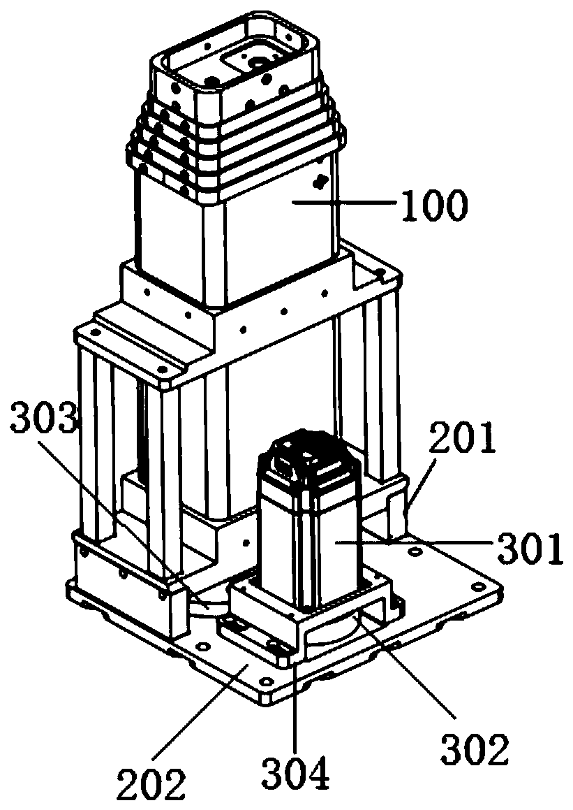
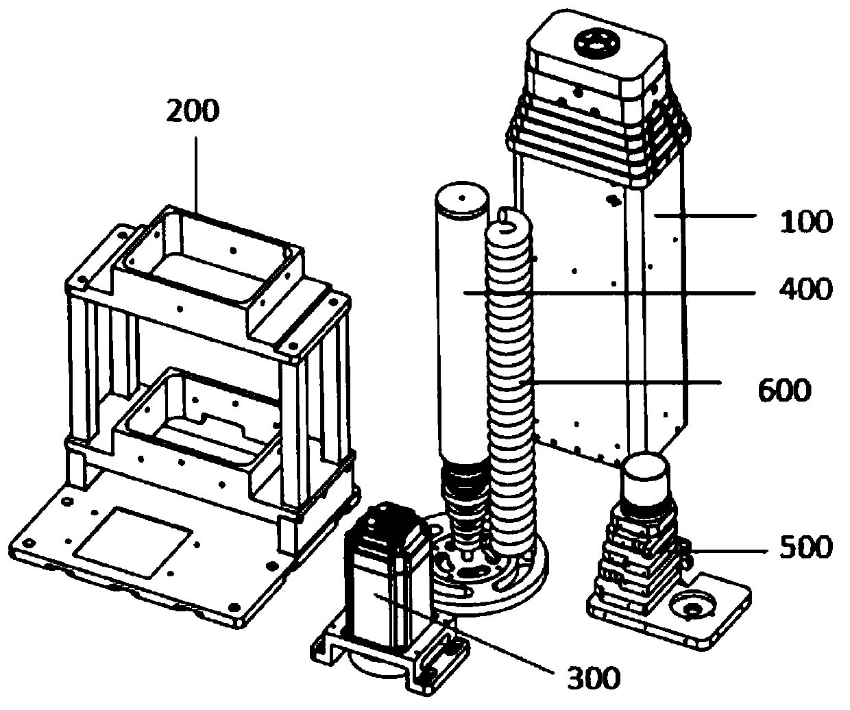
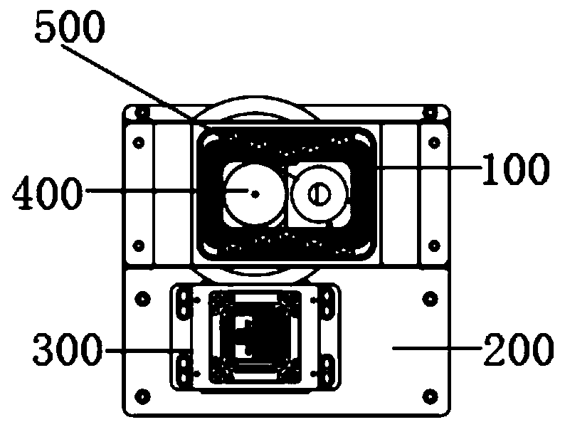
[0038] Such as Figure 1-Figure 3 A light-duty screw lifting mechanism shown includes a lifting barrel module 100 , a driving module 300 , a screw module 400 and a connecting module 500 . This embodiment takes 6 lifting barrels as an example to introduce the light-duty screw-screw lifting mechanism of the present invention. The screw module 400 is installed in the main body of the lifting bucket module, the screw module 400 and the main body of the lifting bucket module are connected through the connection module 500, and the driving module 300 and the main body of the lifting bucket module are fixed together on the fixing frame 200 of the lifting bucket. The motor 301 in the driving module 300 transmits power to the screw module 400 through two transmission gears (the first transmission gear 302 and the second transmission gear 303 ), and the rotation of the screw rod dri...


PUM


Abstract

The invention relates to a light lead screw lifting mechanism which comprises a lifting bucket module, a driving module, a lead screw module and a connecting module. The lifting bucket module comprises n lifting buckets. The driving module comprises a motor, a transmission gear I and a transmission gear II. The lead screw module comprises n lead screws; the first end of the lead screw on the innerside stretches outward from the first end of the adjacent lead screw on the outer side; except the innermost lead screw, the first ends of the rest of lead screws are provided with lead screw nuts; aguide nut is mounted at the tail end of each lead screw; and the first end of the innermost lead screw is connected to the transmission gear II; the connecting module comprises n connecting plates; except the connecting plate in the innermost lifting bucket, bearings are mounted on the connecting plates in the rest of lifting buckets; the connecting plate in the outermost lifting bucket is connected to the lead screw nut on the outermost lead screw; and except the lead screw nut on the outermost lead screw, the rest of lead screw nuts are assembled in the bearings successively. The light leadscrew lifting mechanism has the characteristics of being small in size, light in weight, large in stroke, stable and reliable to operate and the like.

Description

technical field [0001] The invention relates to the technical field of robots, in particular to a light-duty screw rod lifting mechanism. Background technique [0002] With the rapid development of the robot industry, the area covered by the industry is getting larger and larger, and the performance requirements of robots are becoming more and more stringent. Robots are required to be small in size, light in weight, and safe and reliable in use. For example, inspection robots in the electric power and rail transit industries, due to the requirements of their working conditions, the robot needs to inspect a large range of heights. The stroke from the lowest point to the highest point is 1600mm, and some special environments even reach 2000mm. This is a big challenge for the lifting system of the robot, which needs to be multi-level. The multi-stage lifting mechanisms on the market now have wire rope lifting, belt drive lifting, chain lifting and screw rod lifting, but each h...

Claims


Application Information

Patent Timeline
Patent Type & Authority Applications(China)
IPC IPC(8): B66F3/44
CPCB66F3/44
Inventor 许志瑜王勇周凤学李春生张鑫振
Owner HEFEI CSG SMART ROBOT TECH CO LTD
Features
  • Generate Ideas
  • Intellectual Property
  • Life Sciences
  • Materials
  • Tech Scout
  • Unparalleled Data Quality
  • Higher Quality Content
  • 60% Fewer Hallucinations
Learn More