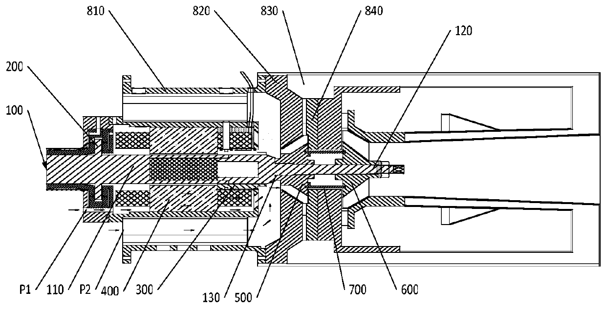
Rotor system and micro gas turbine generator set
A rotor and compressor technology, applied in gas turbine installations, machines/engines, mechanical equipment, etc., can solve the problems of lengthening, bad, and affecting the stability of the rotor system, and achieve short axial dimensions and good dynamic characteristics. Effect
- Summary
- Abstract
- Description
- Claims
- Application Information
AI Technical Summary
Problems solved by technology
Method used
Image
Examples
Embodiment 1
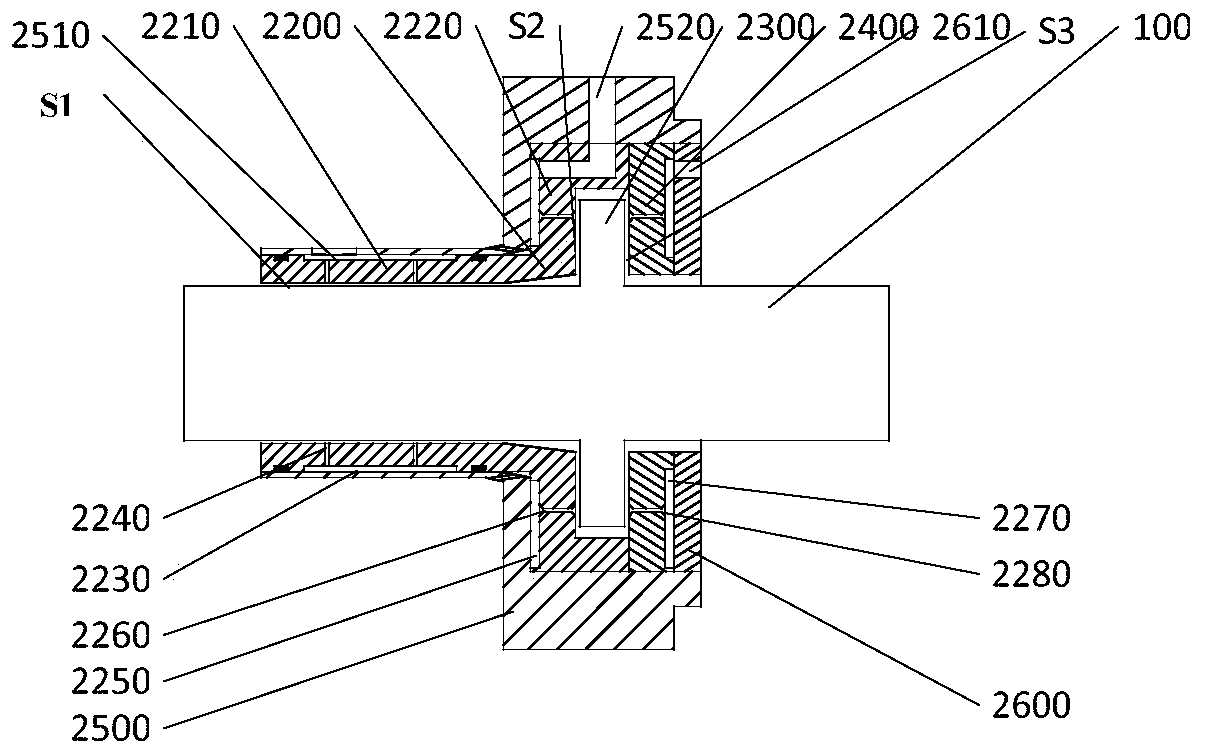
[0087] In this embodiment, a structure of an integrated bearing 200 is provided. The integrated bearing 200 adopts an integrated air bearing, which not only has a radial support function, but also has an axial support function.
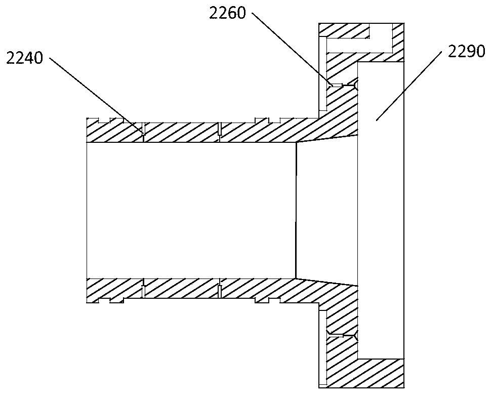
[0088] Among them such as figure 2 , 3 As shown, the integrated bearing 200 includes: a first bearing body 2200, a thrust plate 2300, and a second bearing body 2400; the thrust plate 2300 is fixedly connected or integrally formed with the rotating shaft 100; the first bearing body 2200 and the second bearing body 2400 are equally fitted Set on the rotating shaft 100 and located on both sides of the thrust plate 2300; the first bearing body 2200 has a radial bearing part 2210 and a thrust bearing part 2220 integrally formed, and the radial bearing part 2210 and the rotating shaft 100 have a predetermined radial clearance in the radial direction S1, the thrust bearing part 2220 is installed opposite to the thrust plate 2300 in the axial direction and...
Embodiment 2
[0127] In this embodiment, a motor 400 structure is provided, and the motor 400 adopts a back-winding method to form a first air inlet P1 on the stator of the motor.
[0128] Specifically, such as Figure 9 As shown, the motor 400 includes: a motor stator 410, a motor rotor (not shown in this figure), and a motor housing 430. The motor stator 410 is sleeved on the rotating shaft 100, and maintains a certain gap with the rotating shaft 100 in the radial direction. The casing 430 is covered on the outer periphery of the motor stator 410, and the motor stator 410 is provided with a plurality of air inlets 440 axially penetrating through the motor stator 410, and the air inlets 440 are the first air inlets. Road P1.
[0129] Since the air inlet 440 is provided, the air intake of the compressor 500 can enter the compressor 500 through the air inlet 440, so that the air intake of the compressor 500 is more sufficient, and at the same time, the normal temperature air passing through...
Embodiment 3
[0141] In this embodiment, an anti-rotation structure for the integrated bearing 200 in the second embodiment is provided. A first anti-rotation member 2900 is provided between the first bearing housing 2500 and the first bearing body 2200, and / or between the first bearing housing 2500 and the second bearing body 2400, and the first The anti-rotation member 2900 is used for fixing the first bearing body 2200 relative to the first bearing housing 2500 and / or the second bearing body 2400 relative to the first bearing housing 2500 in the circumferential direction.
[0142] Specifically, one end of the first anti-rotation member 2900 is fixedly connected or integrally formed with the first bearing housing 2500, and the other end of the first anti-rotation member 2900 is detachably connected with the first bearing body 2200 or the second bearing body 2400; or One end of the first anti-rotation member 2900 is detachably connected to the first bearing housing 2500, and the other end ...
PUM
 Abstract
Description
Claims
Application Information
 - R&D
- Intellectual Property
- Life Sciences
- Materials
- Tech Scout
- Unparalleled Data Quality
- Higher Quality Content
- 60% Fewer Hallucinations
Browse by: Latest US Patents, China's latest patents, Technical Efficacy Thesaurus, Application Domain, Technology Topic, Popular Technical Reports.
© 2025 PatSnap. All rights reserved.Legal|Privacy policy|Modern Slavery Act Transparency Statement|Sitemap|About US| Contact US: help@patsnap.com


