
Interlocking retaining nut

A nut and locking technology, applied in the direction of nuts, screws, bolts, etc., can solve problems such as equipment damage or even accidents, and increase maintenance cycle time

Inactive Publication Date: 2020-04-21
李先登
View PDF6 Cites 0 Cited by
  • Summary
  • Abstract
  • Description
  • Claims
  • Application Information

AI Technical Summary

Problems solved by technology

[0003] The loosening of nuts and screws caused by mechanical vibration is one of the more common harmful phenomena in the field of mechanical technology. It will cause damage or even accidents to various equipment. Summarize and formulate equipment maintenance management methods and system regulations, and carry out regular maintenance and periodic maintenance of equipment according to the plan, especially in some high-end mechanical equipment technical fields, such as high-speed rail, etc. Especially high technical requirements for anti-retraction, eager to obtain more technical support for non-retraction and zero-loose connections, so as to greatly increase the maintenance cycle time of equipment, reduce maintenance workload, and simplify maintenance methods. With the advancement of industrial technology, materials and lubrication After the great achievements have been made, it provides favorable conditions for greatly extending the maintenance cycle of maintenance equipment, but there must be subversive technological innovations for the loosening of key parts, so that the problem of free loosening of vibration can be reduced to zero, and the problem of mechanical loosening caused by itself can be eliminated. Various unexpected events happen

Method used


Image

  • Interlocking retaining nut

Examples


Embodiment 1

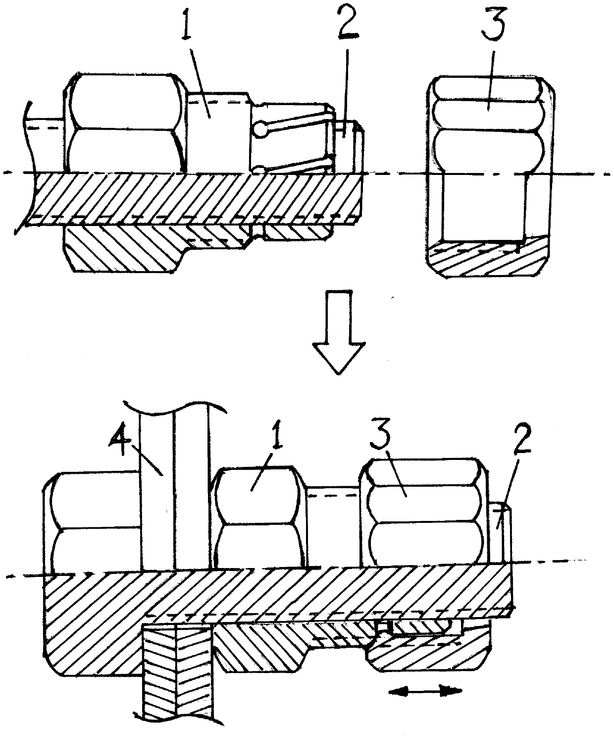
[0011] Embodiment 1: The process of stopping and releasing the stop-back of the three-step interlocking stop-back nut, see figure 1 .

[0012] figure 1 It is a schematic diagram of the shape and assembly relationship of the interlocking anti-retraction nuts of the three ladders. After the two assembly connection seats (4) are accurately positioned, the bolts (2) are threaded, and then the nut A (1) is tightened, and the nut A (1) is confirmed. After the tightness meets the requirements, tighten nut B(3) upwards on nut A(1). After confirming that the tightness of nut B(3) and nut A(1) meets the requirements, nut A(1), bolt (2) Nut A (1) and bolt (2) are bidirectionally interlocked between nut B(3), and nut A(1) and nut B(3) are bidirectionally interlocked. The three-part interlocking relationship is established. Finished, now the nut A (1), the bolt (2), and the nut (3) all have the back-stop function;

[0013] Nut B(3) makes nut A(1)'s small-diameter circular body with groo...


PUM


Abstract

The invention relates to an interlocking retaining nut and belongs to the technical field of machinery. The interlocking retaining nut is formed by combining a three-step type nut A and an indent vertebral locking nut B, a hexagonal loosening and tightening thick column surface, a loosening and tightening screw medium column surface and a locking retreating thin groove column surface are arrangedon the outer portion of the nut A, the three columns are integral, share the axial line, share the inner nut line and share a screw rod for matched loosening and tightening; an even number of small holes with the diameter being D are evenly formed in the perpendicular axis direction between the medium column surface and the unthreaded column surface, wherein D is larger than or equal to L; the nutis is fastened on a bolt, and a small inner vertebral locking hoop of the nut B and the unthreaded thin groove column surface of the nut A are in interference fit; the nut B is screwed on the nut A,the small inner vertebral locking hoop of the nut B presses the thin groove column end of the nut A in a collecting mode to change the nut A into a slight platform pipe with the thin vertebral end tightly pressing the bolt to achieve pressing dead point type interlocking between the two screw surfaces, and the locking hoop of the nut B is locked through groove line exposure and collected pressingof the two sides; and the nut B can be manually unlocked.

Description

technical field [0001] The invention relates to an interlocking backstop nut, which belongs to the technical field of machinery. [0002] technical background [0003] The loosening of nuts and screws caused by mechanical vibration is one of the more common harmful phenomena in the field of mechanical technology. It will cause damage or even accidents to various equipment. Summarize and formulate equipment maintenance management methods and system regulations, and carry out regular maintenance and periodic maintenance of equipment according to the plan, especially in some high-end mechanical equipment technical fields, such as high-speed rail, etc. Especially high technical requirements for anti-retraction, eager to obtain more technical support for non-retraction and zero-loose connections, so as to greatly increase the maintenance cycle time of equipment, reduce maintenance workload, and simplify maintenance methods. With the advancement of industrial technology, materials ...

Claims


Application Information

Patent Timeline
IPC IPC(8): F16B39/30F16B39/38F16B39/12
CPCF16B39/126F16B39/30F16B39/38
Inventor 李先登
Owner 李先登
Learn More