
Eureka
For R&D, Eureka makes reading and utilizing patents & technical documents easy.
Eureka AIR
Designed for self-driven R&D workflows. Generate viable solutions, solve complex R&D challenges, empower your innovation with AI.

Eureka Materials
Designed for material experts only. Revolutionize your material R&D, from search, analyze, to developing new materials.

TechResearch
Generate reliable direction feasibility study reports for your R&D in just a few steps.

TechSeek
Discover and master advanced knowledge NOW. Basics, ideas, possibilities, all at once.

TechMind
As an expert in R&D Theories, TechMind can generates customized viable solutions instantly.

TechRisk
Analyze your overall solution with one click, know your potential R&D risks in advance.

TechMonitor
Get weekly tech updates, stay abreast of the latest tech innovations and key insights.
Inter-tooth transmission structure of speed reducer
A technology of transmission structure and reducer, applied in the direction of gear transmission, transmission, mechanical equipment, etc., can solve the problem of large transmission friction between the teeth of the reducer
- Summary
- Abstract
- Description
- Claims
- Application Information
AI Technical Summary
Problems solved by technology
Method used
Image

Examples
Embodiment 1
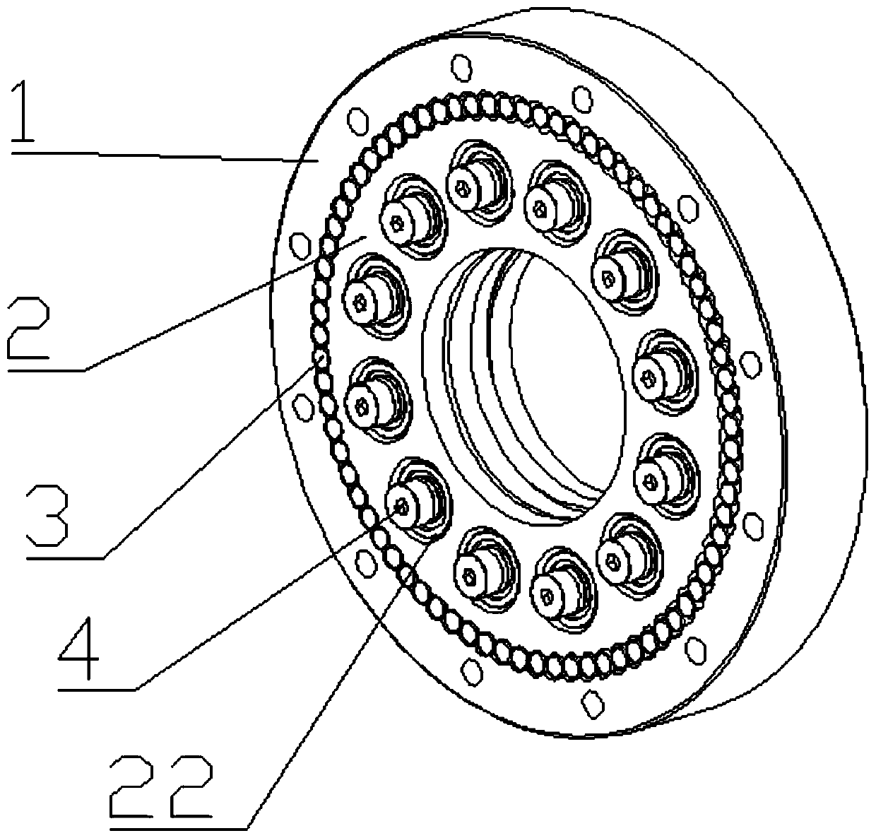
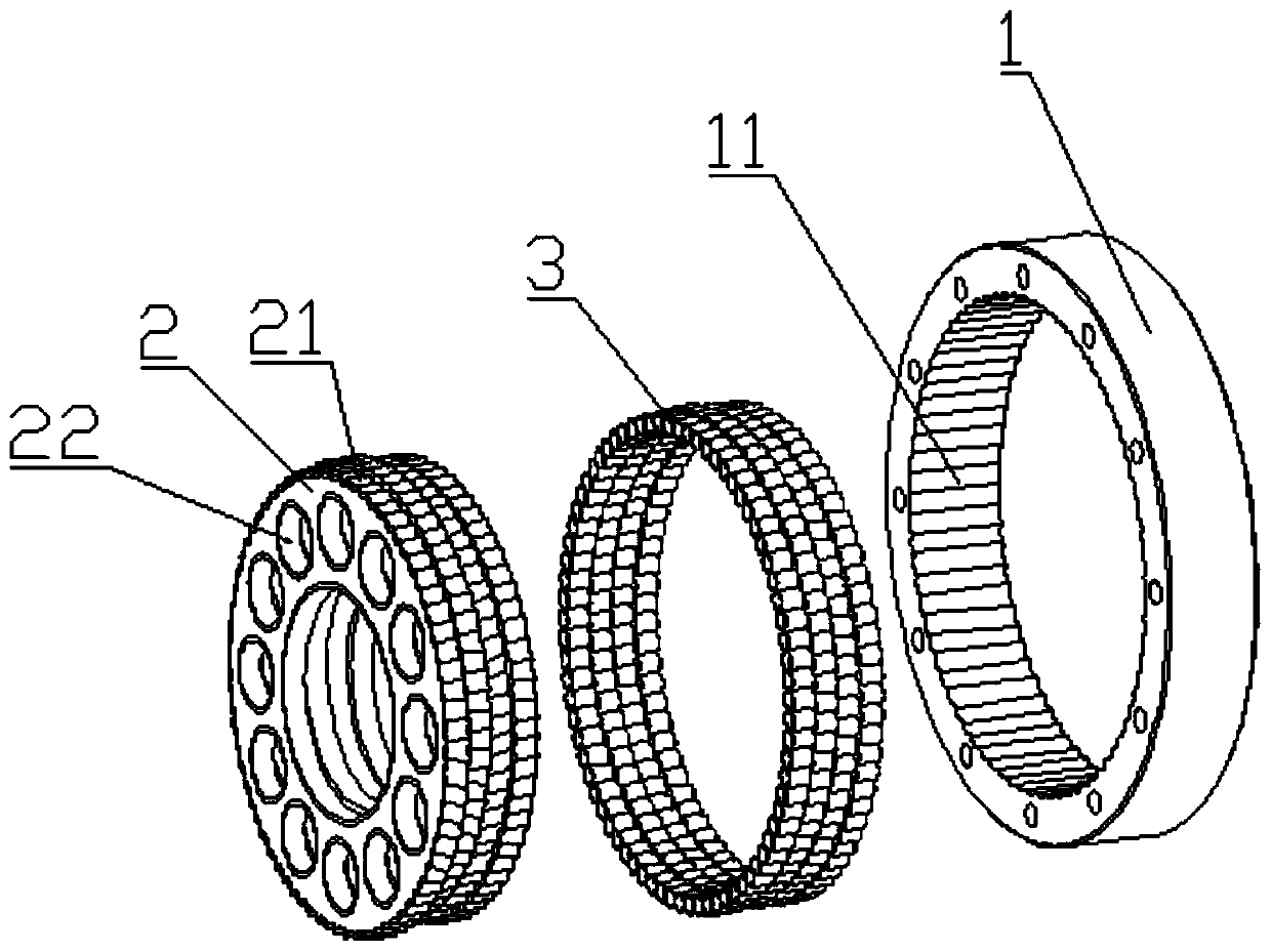
[0023] Embodiment one: if figure 1 and 2 As shown, on the basis of the above technology, the inter-tooth transmission structure also has a transmission structure similar to the cycloid reducer, as follows:
[0024] The inner wheel 2 is selected as a cycloidal wheel, and the outer wheel 1 is selected as a pin-toothed housing.
[0025] In this embodiment, at least three support holes 22 are opened on the inner wheel 2 , and the support holes 22 are supported by ball bearings 4 .
[0026] In this embodiment, the number of said inner wheels 2 is four.
Embodiment 2
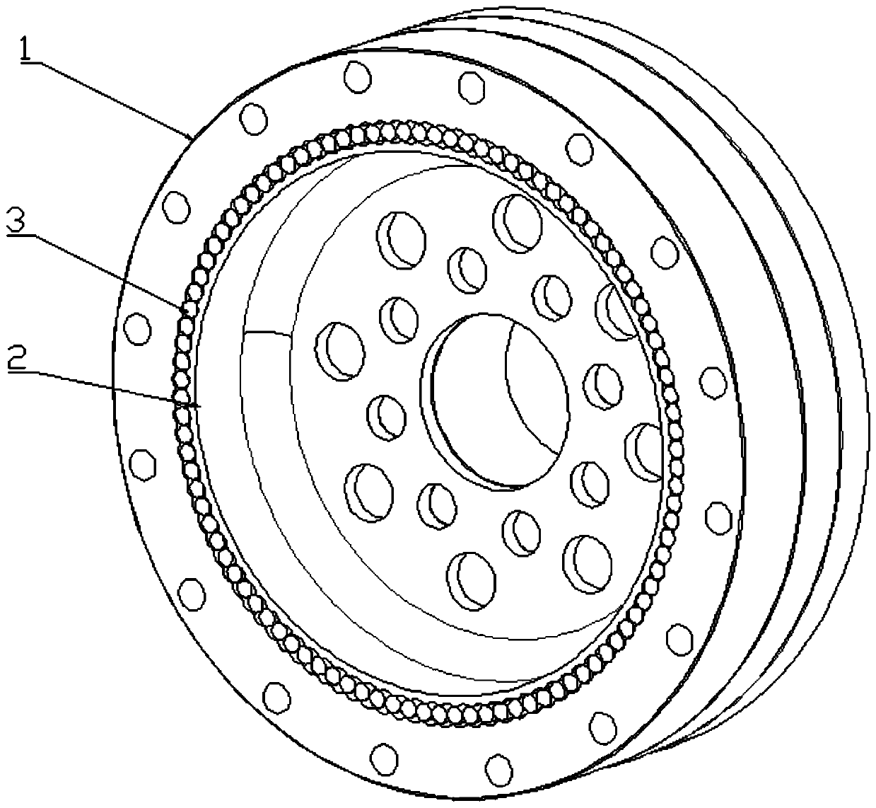
[0027] Embodiment two: if image 3 and 4 As shown, on the basis of the above technology, the inter-gear transmission structure also has a transmission structure similar to a harmonic reducer, specifically as follows: the inner wheel 2 is a flexible gear, and the outer wheel 1 is a rigid gear.
[0028] The rolling element 3 is a cylindrical rolling element. Specifically, the cylindrical rolling element is a rigid cylindrical rolling ball, and the type of the cylindrical rolling element may be a rolling needle, a rolling ball or a miniature rolling bearing.
PUM
 Abstract
Description
Claims
Application Information
 - R&D Engineer
- R&D Manager
- IP Professional
- Industry Leading Data Capabilities
- Powerful AI technology
- Patent DNA Extraction
Browse by: Latest US Patents, China's latest patents, Technical Efficacy Thesaurus, Application Domain, Technology Topic, Popular Technical Reports.
© 2024 PatSnap. All rights reserved.Legal|Privacy policy|Modern Slavery Act Transparency Statement|Sitemap|About US| Contact US: help@patsnap.com