
Control method and control device of electromagnetic valve and vehicle

A control method and control device technology, applied in the direction of valve operation/release device, valve device, valve details, etc., can solve the problems of being unable to control the amplitude and frequency of parasitic current, and unable to independently adjust the amplitude and frequency of parasitic current, etc., To achieve the effect of improving the dynamic response characteristics and simplifying the algorithm

Inactive Publication Date: 2020-04-21
WEICHAI POWER CO LTD +1
View PDF5 Cites 6 Cited by
  • Summary
  • Abstract
  • Description
  • Claims
  • Application Information

AI Technical Summary

Problems solved by technology

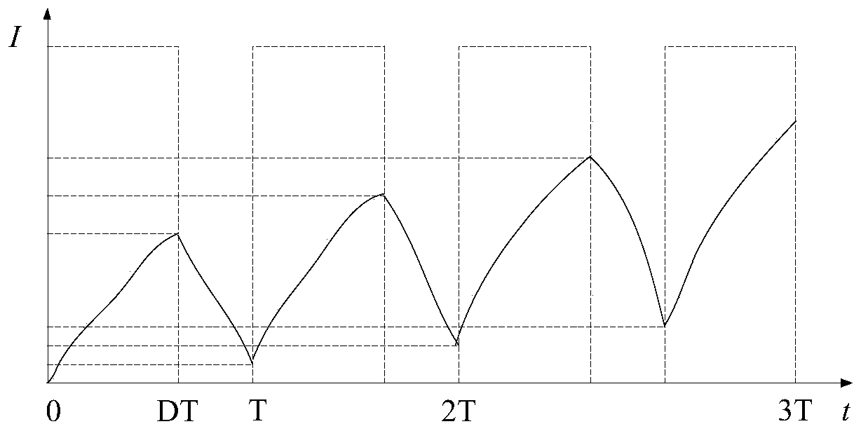
The amplitude and frequency of the parasitic current are determined by the amplitude, frequency and duty cycle of the PWM signal. When the main current of the solenoid valve needs to be changed to control the open state of the solenoid valve, the parasitic current will also change with the PWM signal. and change, so that the amplitude and frequency of the parasitic current cannot be adjusted independently, so the amplitude and frequency of the parasitic current cannot be controlled according to the hysteresis effect of the solenoid valve

Method used


Image

  • Control method and control device of electromagnetic valve and vehicle
  • Control method and control device of electromagnetic valve and vehicle
  • Control method and control device of electromagnetic valve and vehicle

Examples


Embodiment 1

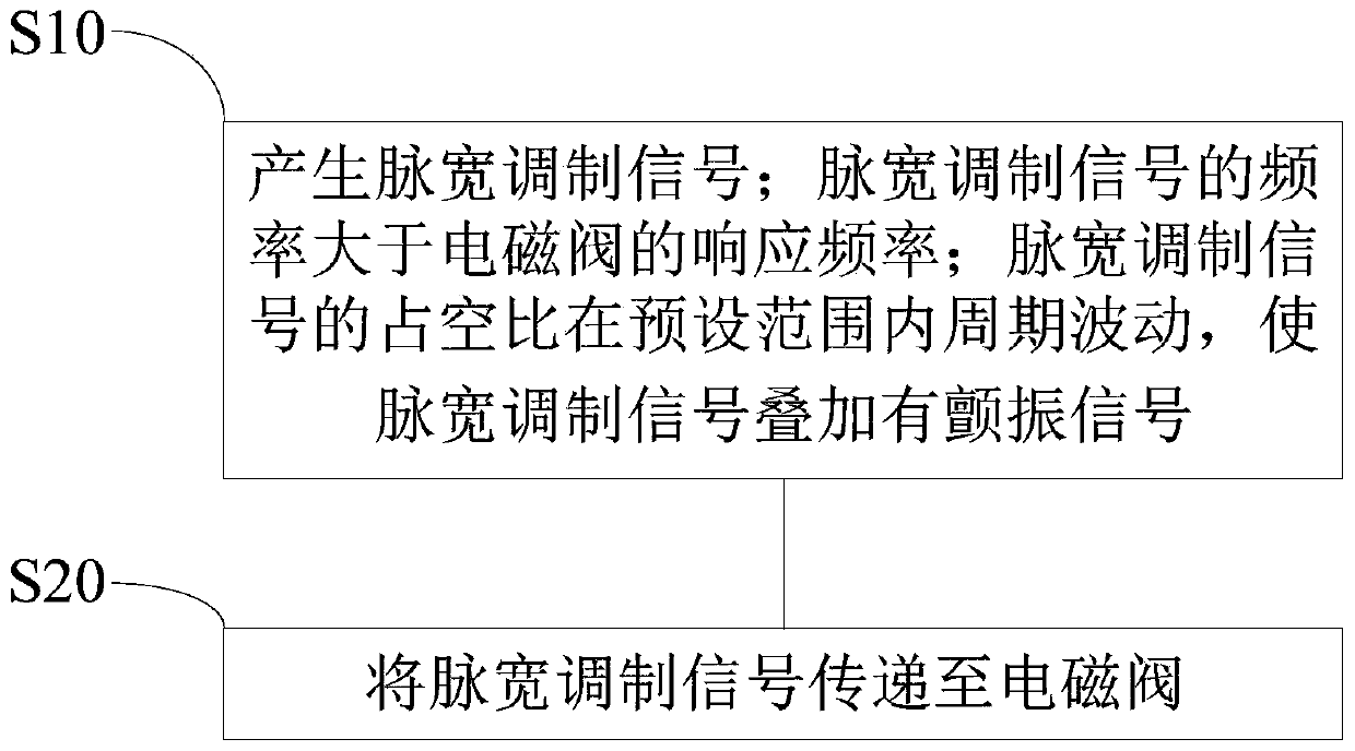
[0024] figure 2 It is a flowchart of a control method of a solenoid valve in Embodiment 1 of the present invention, and the control method can be executed by a control device of a solenoid valve, such as figure 2 As shown, the control method of the solenoid valve includes:

[0025] S10, generating a pulse width modulation signal; the frequency of the pulse width modulation signal is greater than the response frequency of the solenoid valve; the duty cycle of the pulse width modulation signal fluctuates periodically within a preset range, so that the pulse width modulation signal is superimposed with a flutter signal.

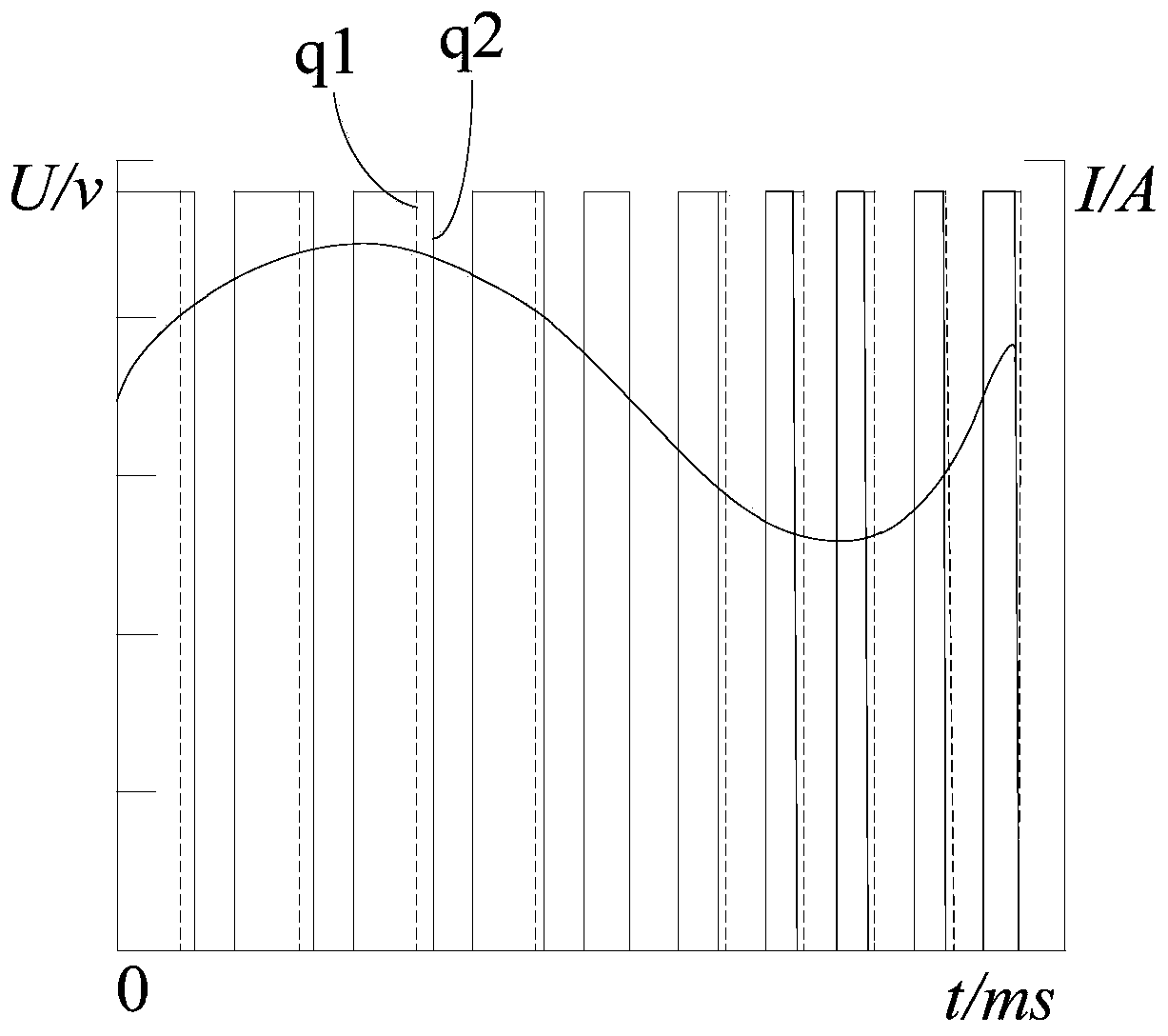
[0026] Specifically, the PWM signal can be used to control the open state of the solenoid valve. When the current output by the PWM signal is larger, the solenoid valve is opened more. The current output by the PWM signal increases with the increase of the duty cycle of the PWM. And the higher the frequency of the PWM is, the better the linearity of the cur...

Embodiment 2

[0039] Figure 6 It is a schematic structural diagram of a control device for a solenoid valve provided in Embodiment 2 of the present invention, as shown in Figure 6 As shown, the control device of the solenoid valve includes:

[0040] The pulse width modulation signal generating module 10 is used to generate a pulse width modulation signal; the frequency of the pulse width modulation signal is greater than the response frequency of the solenoid valve; the duty cycle of the pulse width modulation signal fluctuates periodically within a preset range, so that the pulse width modulation signal Flutter signal superimposed;

[0041] The transmission module 20 is used for transmitting the pulse width modulation signal to the solenoid valve.

[0042] In the technical solution of Embodiment 2 of the present invention, the pulse width modulation signal is generated by the pulse width modulation signal generation module; and the frequency of the pulse width modulation signal is grea...

Embodiment 3

[0050] Embodiment 3 of the present invention provides a vehicle, which includes the solenoid valve control device as described in Embodiment 2, with one-to-one technical features, and can achieve the same technical effect as that achieved by any technical solution in Embodiment 2 The effect of implementation will not be repeated here.


PUM


Abstract

The embodiment of the invention discloses a control method and a control device of an electromagnetic valve and a vehicle. The control method of the electromagnetic valve comprises the following steps: generating a pulse width modulation signal, wherein the frequency of the pulse width modulation signal is greater than the response frequency of the electromagnetic valve and the duty ratio of the pulse width modulation signal fluctuates periodically within a preset range so that the pulse width modulation signal is superposed with a flutter signal; and transmitting the pulse width modulation signal to the electromagnetic valve. The amplitude and the frequency of the flutter signal are respectively determined by modulating the periodic fluctuation of the duty ratio of the PWM signal in the preset range and the fluctuation range and the fluctuation period of the duty ratio of the PWM signal so that the independent adjustment of the amplitude and the frequency of the flutter signal is realized. The algorithm of the flutter signal is simplified on the basis of solving the problem of hysteresis of the electromagnetic valve due to static friction of the system or parasitic flutter of theelectromagnetic valve, and the amplitude and the frequency of the flutter signal can be better controlled according to the requirement of the hysteresis effect and thus the dynamic response characteristic of the electromagnetic valve can be better improved.

Description

technical field [0001] Embodiments of the present invention relate to the technical field of solenoid valve driving, and in particular to a control method, a control device and a vehicle of a solenoid valve. Background technique [0002] In the hydraulic system, the solenoid valve is used to realize the on-off of the liquid circuit or the change of the liquid flow direction. The solenoid valve generally has a spool that can slide under the electromagnetic force of its solenoid coil, and the solenoid valve is controlled by the sliding spool. on and off. Because the magnet material has hysteresis characteristics, and the valve core has to overcome a certain static friction force in the solenoid valve system during the process of sliding from rest, the solenoid valve has a viscous effect and hysteresis, which reduces the dynamic response performance of the solenoid valve. [0003] In the prior art, the hysteresis effect of the solenoid valve can be improved by using a pulse wi...

Claims


Application Information

Patent Timeline
IPC IPC(8): F16K31/06
CPCF16K31/06F16K31/0675
Inventor 陈岩孙光明李杰
Owner WEICHAI POWER CO LTD
Learn More