
Large-scale high-speed rotary equipment error measurement and separation method based on laser sensing

A technology of laser sensing and error measurement, which is applied in the direction of measuring devices, optical devices, complex mathematical operations, etc., can solve the problems of large errors, achieve the separation of errors, improve the accuracy, and improve the effect of measurement accuracy

Active Publication Date: 2020-04-21
HARBIN INST OF TECH
View PDF6 Cites 1 Cited by
  • Summary
  • Abstract
  • Description
  • Claims
  • Application Information

AI Technical Summary

Problems solved by technology

[0003] In order to solve the problem of large final error in the measurement process, the present invention can further effectively improve the measurement accuracy of the rotor during the measurement process. The present invention provides a large-scale high-speed rotary equipment error measurement and separation method based on laser sensing. The present invention The following technical solutions are provided:

Method used


Image

  • Large-scale high-speed rotary equipment error measurement and separation method based on laser sensing
  • Large-scale high-speed rotary equipment error measurement and separation method based on laser sensing
  • Large-scale high-speed rotary equipment error measurement and separation method based on laser sensing

Examples


specific Embodiment 1

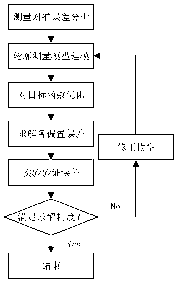
[0038] according to image 3 As shown, a large-scale high-speed rotary equipment error measurement and separation method based on laser sensing includes the following steps:

[0039] Step 1: Analyze the error of large-scale high-speed rotary equipment, and establish a large-scale high-speed rotary equipment error measurement model based on laser sensing;

[0040] The step 1 is specifically:

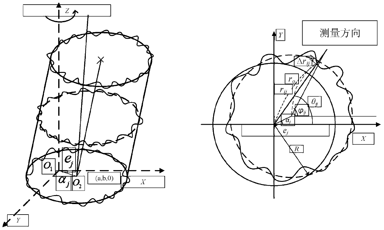
[0041] Step 1.1: Analyze the error of large-scale high-speed rotary equipment, determine the eccentricity error of large-scale high-speed rotary equipment, and express the eccentricity error of large-scale high-speed rotary equipment by the following formula:

[0042]

[0043] Among them, e j Eccentricity error for large high-speed rotary equipment, r ij is the measurement radius, θ ij is the sampling angle, α j is the eccentric angle, Δr ij is the processing error, j is the different section;

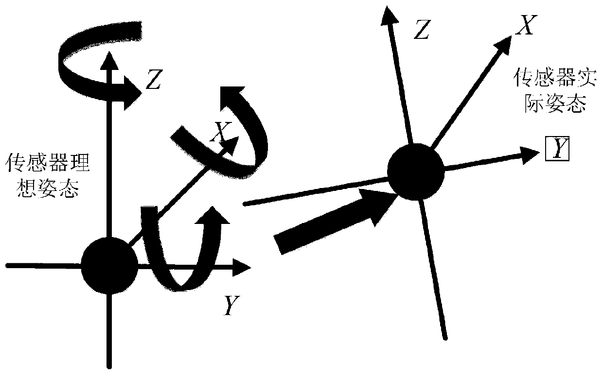
[0044] according to figure 2 As shown, step 1.2: determine the lateral offset erro...


PUM


Abstract

The invention relates to a large-scale high-speed rotary equipment error measurement and separation method based on laser sensing. The large-scale high-speed rotary equipment error measurement and separation method comprises the following steps of: analyzing errors of large-scale high-speed rotary equipment, and establishing a large-scale high-speed rotary equipment error measurement model based on laser sensing; establishing a measurement optimization objective function, and determining a solution bias error; acquiring a precise parameter error value by means of measurement equipment and an implementation platform according to the solution bias error, and performing experimental verification on the solution bias error; and correcting the solution bias error by adopting a correction model,repeating the correction until a precision value is met, and ending the measurement. According to the large-scale high-speed rotary equipment error measurement and separation method, the measurementposition error of the measurement sensor can be obtained, and the error in the measurement process can be effectively compensated, so that the measurement precision is effectively and precisely improved; precise measurement of measured parameters can be realized, and the measurement precision is improved; and different precise models can be established during measurement of different errors, so that the measurement precision is further improved, and the separation of the errors is realized.

Description

technical field [0001] The invention relates to the technical field of error measurement and separation of large-scale high-speed rotary equipment, and relates to a method for error measurement and separation of large-scale high-speed rotary equipment based on laser sensing. Background technique [0002] With the rapid development of science and technology, various measurement equipment are constantly updated, and measurement methods and means are also constantly changing. Accurate calibration and alignment of the sensor is inseparable from the realization of all-round three-dimensional accurate measurement, so as to reduce the influence of measurement error, thereby greatly improving the measurement accuracy and precision of the measured physical quantity. If the measurement equipment is installed incorrectly or the position of the measurement equipment has a large error, the measurement data will be distorted and the results will be invalid. Seriously affect the follow-up...

Claims


Application Information

Patent Timeline
Patent Type & Authority Applications(China)
IPC IPC(8): G01B11/00G01B11/24G06F17/15
CPCG01B11/00G01B11/24G06F17/15
Inventor 刘永猛谭久彬张茂伟孙传智王晓明
Owner HARBIN INST OF TECH
Learn More