Micro-channel structure, fluid testing device and fluid sample injection testing system

A test device and micro-channel technology, applied to instruments, laboratory utensils, analytical materials, etc., can solve the problems of reagent waste and precious reagent accumulation, and achieve the effects of saving test reagents, reducing volume, and simplifying the system structure

Pending Publication Date: 2020-04-21
江苏圣极基因科技有限公司
View PDF4 Cites 1 Cited by
  • Summary
  • Abstract
  • Description
  • Claims
  • Application Information

AI Technical Summary

Problems solved by technology

At present, the control of the flow path is mostly by means of solenoid valves, pinch valves, rotary valves, etc., without exception, all of which require a certain length of flow path to cooperate. It is inevitable that some precious reagents will accumulate in the flow path, resulting in waste of reagents

Method used


Image

  • Micro-channel structure, fluid testing device and fluid sample injection testing system
  • Micro-channel structure, fluid testing device and fluid sample injection testing system
  • Micro-channel structure, fluid testing device and fluid sample injection testing system

Examples


Embodiment Construction

[0032] In order to make the object, technical solution and advantages of the present invention clearer, various embodiments of the present invention will be described in detail below in conjunction with the accompanying drawings. However, those of ordinary skill in the art can understand that, in each implementation manner of the present invention, many technical details are provided for readers to better understand the present application. However, even without these technical details and various changes and modifications based on the following implementation modes, the technical solution claimed in each claim of the present application can be realized.

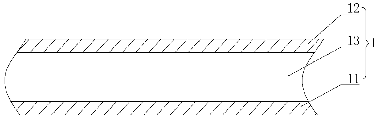
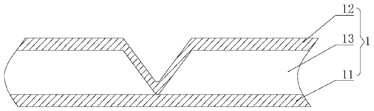
[0033] The first embodiment of the present invention relates to a microchannel structure, such as figure 1 As shown, the micro-channel structure 1 is used to flow test reagents, and at least part of the micro-channel structure 1 can be squeezed.

[0034] Among them, such as figure 1 As shown, the microfluidic channel struc...


PUM


Abstract

The invention relates to the technical field of microfluidic chips, particularly to a micro-channel structure, a fluid testing device and a fluid sample injection testing system. The micro-channel structure comprises a matrix material and a flow channel. The matrix material comprises a hard base layer and a flexible base layer attached to the hard base layer, a fluid channel is arranged between the hard base layer and the flexible base layer, the flexible base layer can be extruded to be attached to the hard base layer under the action of external force relative to the direction of the hard base layer; and after the external force is removed, the flexible base layer returns to the initial state. Compared with the prior art, the micro-channel structure has the following advantages: when a test reagent enters the microfluidic chip by means of the fluid channel, the fluid channel can be cut off and conducted by directly extruding or releasing the flexible base layer, so that devices suchas an electromagnetic valve, a conversion valve and the like can be omitted, the volume of an extra flow path is greatly reduced while the system structure is simplified, and the purpose of saving a test reagent is achieved.

Description

technical field [0001] Embodiments of the present invention relate to the technical field of microfluidic chips, and in particular to a microfluidic channel structure, a fluid testing device, and a fluid sampling testing system. Background technique [0002] Microfluidic chip technology is one of the rapidly developing frontier fields of high-tech and interdisciplinary science and technology. It is an important technical platform for the research of signal detection and processing methods in life sciences, chemical sciences and information sciences. However, the inventors found that in this technology, it is usually necessary to accurately and effectively control the transportation and mixing of reactants and sample reagents in the pipeline, and the control of the flow path has become the key to this technology. At present, the control of the flow path is mostly by means of solenoid valves, pinch valves, rotary valves, etc., without exception, all of which require a certain ...

Claims


Application Information

Patent Timeline
Patent Type & Authority Applications(China)
IPC IPC(8): G01N35/00G01N35/10B01L3/00
CPCG01N35/00G01N35/1009G01N35/10B01L3/502723G01N2035/00247G01N2035/1034B01L2300/123
Inventor 刘亚吴东平景奉香徐刚伟
Owner 江苏圣极基因科技有限公司
Why Eureka
Try Eureka