
Low-speed stop valve group

A shut-off valve and valve cavity technology, applied in the direction of lift valve, balance valve, valve device, etc., can solve the problems of emulsion leakage in the liquid supply pipeline, affecting normal work, difficult to screw the shut-off valve, etc., to reduce the labor intensity of operation. , Improve safety and reduce impact

Pending Publication Date: 2022-06-07
BEIJING HUAHAI MACHINERY
View PDF5 Cites 0 Cited by
  • Summary
  • Abstract
  • Description
  • Claims
  • Application Information

AI Technical Summary

Problems solved by technology

[0004] In view of the above-mentioned related technical solutions, the inventor found that: when the working face is facing maintenance or emulsion leakage occurs in the liquid supply pipeline, the supply of emulsion is often terminated by directly shutting down the central pump station, but this often affects other working faces normal work; but if the shut-off valve is directly installed on each liquid supply pipeline to realize the separate cut-off of the corresponding liquid supply pipeline, it is difficult to screw the shut-off valve due to the great pipeline pressure acting on the spool of the shut-off valve, And it is easy to cause safety hazard

Method used


Image

  • Low-speed stop valve group
  • Low-speed stop valve group
  • Low-speed stop valve group

Examples


Embodiment 2

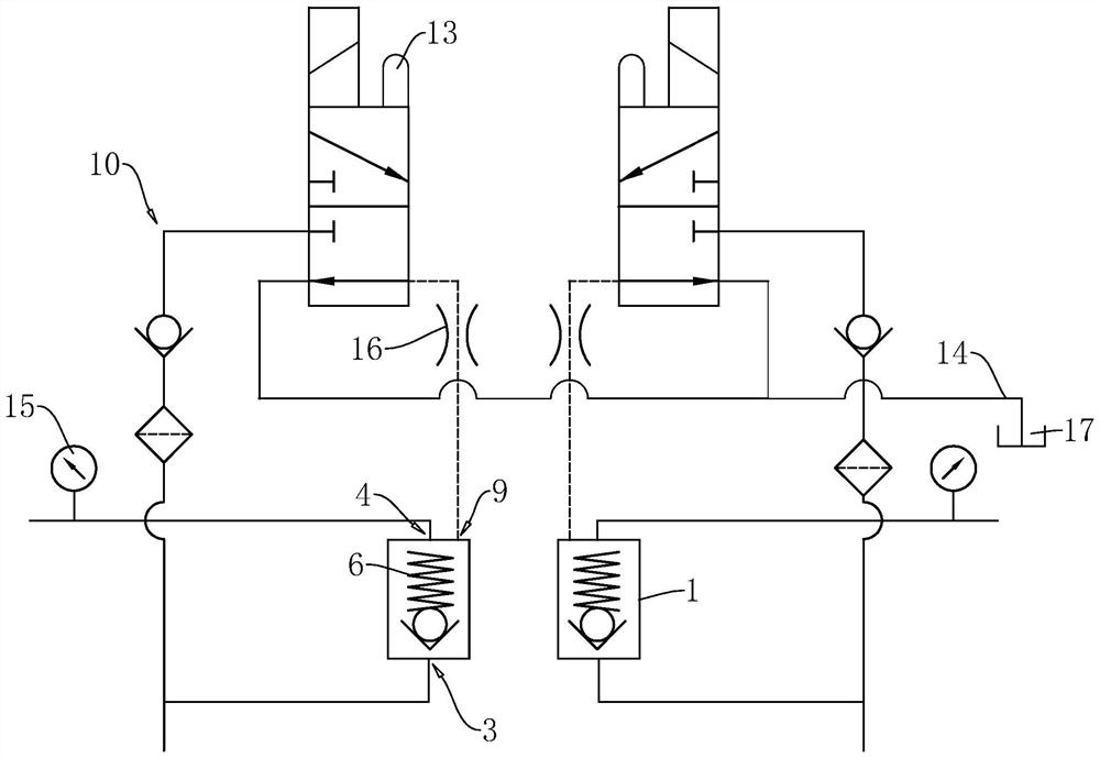
[0048] refer to figure 1 and image 3 , the difference between this embodiment and the first embodiment is that the control oil circuit 10 is different. Specifically, the control oil circuit 10 includes a two-position three-way solenoid valve 13 coupled with a central controller (not shown in the figure). One of the ports of the solenoid valve 13 is communicated with the liquid inlet 3, and the other port on the same side of the two-position three-way solenoid valve 13 is provided with a pressure relief port 14, and the pressure relief port 14 can lead to the emulsion tank 17. The interface on the opposite side of the three-way solenoid valve 13 is communicated with the control liquid port 9; the central controller is connected to the central console for man-machine interaction for communication. It is realized by the way of optical fiber ring network transmission communication.

[0049] In addition, three centralized control stations are provided in the central pumping stat...


PUM


Abstract

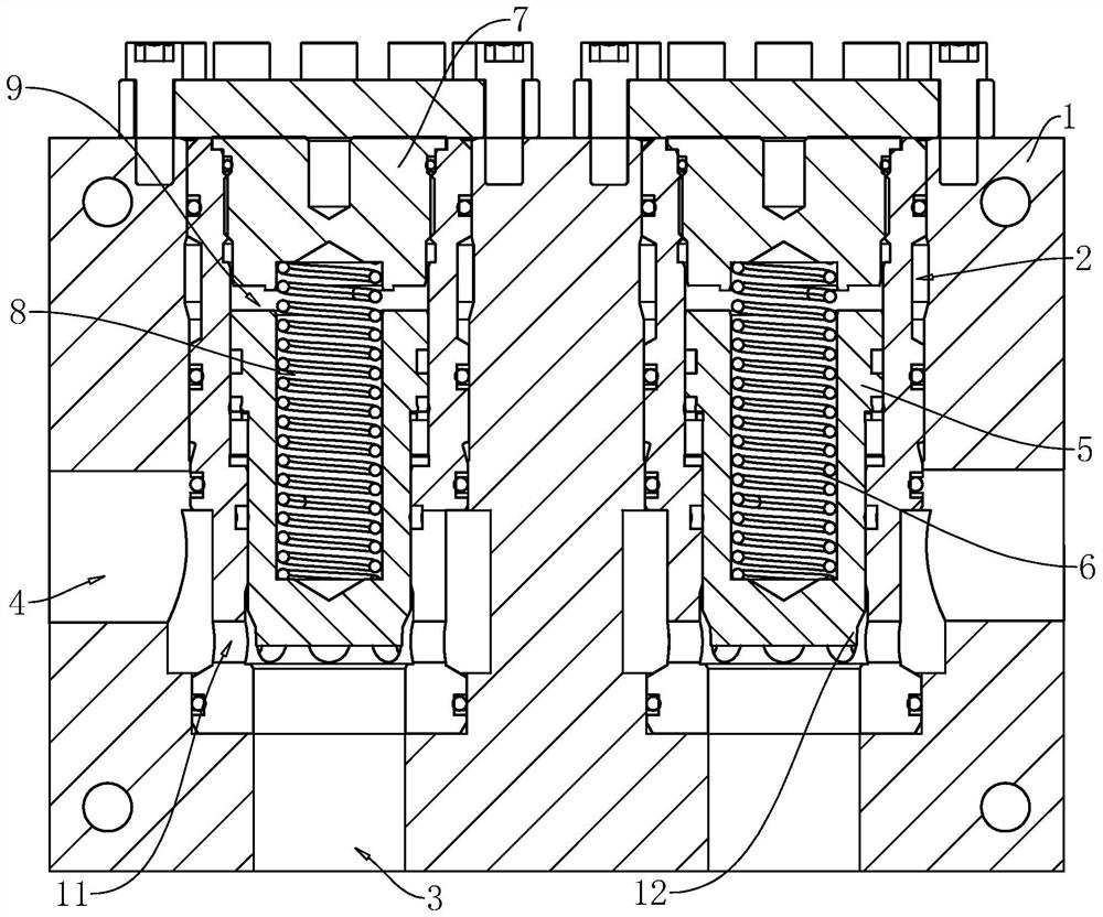
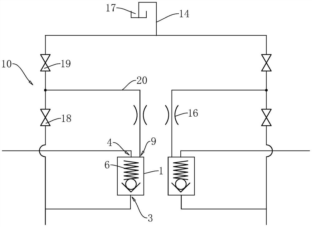
The invention relates to the field of high-pressure system cut-off valves, in particular to a low-speed cut-off valve bank which is characterized in that the low-speed cut-off valve bank comprises a valve body, a valve cavity, a liquid inlet and a liquid outlet are formed in the valve body, the liquid inlet and the liquid outlet are communicated with the valve cavity, and a valve element used for enabling the liquid inlet and the valve cavity to be connected and disconnected is arranged in the valve cavity; the end, away from the liquid inlet, of the valve cavity is closed, a compression spring is fixed between the closed end of the valve cavity and the valve element, a liquid inlet groove is formed in the end, away from the liquid inlet, of the valve element, and a control liquid opening communicated with the liquid inlet groove is formed in the valve body. The low-speed stop valve group further comprises a control oil way used for controlling manual / automatic connection and disconnection of the liquid port and the liquid inlet. The purpose of conveniently cutting off a single high-pressure and large-flow liquid supply pipeline is achieved.

Description

technical field [0001] The present application relates to the field of high-pressure system shut-off valves, in particular to a slow shut-off valve group. Background technique [0002] As an important part of the mechanization of fully mechanized coal mining, the intelligent high pressure and large flow remote centralized liquid supply system can improve the production efficiency of coal mines, shorten labor time, ensure safe production, improve economic and social benefits, and ensure stable coal supply. [0003] A mine system recorded in the related art includes a central pumping station and a working face. The central pumping station is connected with a liquid supply pipeline for conveying the emulsion to the working face. After pressurization, it is transported to the working face through the liquid supply pipeline to provide power for the hydraulic support; the working surface and the liquid supply pipeline are often provided with multiple ones, and each liquid supply p...

Claims


Application Information

Patent Timeline
Patent Type & Authority Applications(China)
IPC IPC(8): F16K17/04F16K17/164F16K31/14F16K37/00F16K47/02F16K1/38F16K1/42F15B13/02F15B20/00
CPCF16K17/0473F16K17/164F16K1/385F16K1/42F16K31/14F16K47/023F16K37/0091F15B13/02F15B20/005
Inventor 杜建华杨淑芳王燕丽胡燕
Owner BEIJING HUAHAI MACHINERY
Learn More