Nanoparticle production reactor

A nanoparticle and reactor technology, applied in the field of nanoparticle production reactors, can solve problems such as lens contamination

Active Publication Date: 2020-04-21
LG CHEM LTD
View PDF11 Cites 0 Cited by
  • Summary
  • Abstract
  • Description
  • Claims
  • Application Information

AI Technical Summary

Problems solved by technology

However, conventional reactors cannot completely prevent nanoparticles from flowing to the lens side, and thus the lens is contaminated with nanoparticles, so continuous operation is impossible.

Method used


Image

  • Nanoparticle production reactor
  • Nanoparticle production reactor
  • Nanoparticle production reactor

Examples


Embodiment Construction

[0023] Hereinafter, a reactor for nanoparticle production according to an embodiment of the present invention will be described in detail with reference to the accompanying drawings.

[0024] In addition, regardless of the reference numerals, the same or similar reference numerals are assigned to the same or corresponding parts, redundant description will be omitted, and the size and shape of each constituent member shown may be enlarged or reduced for convenience of description. .

[0025] In this paper, the reactor used for nanoparticle production is related to the laser pyrolysis reaction equipment.

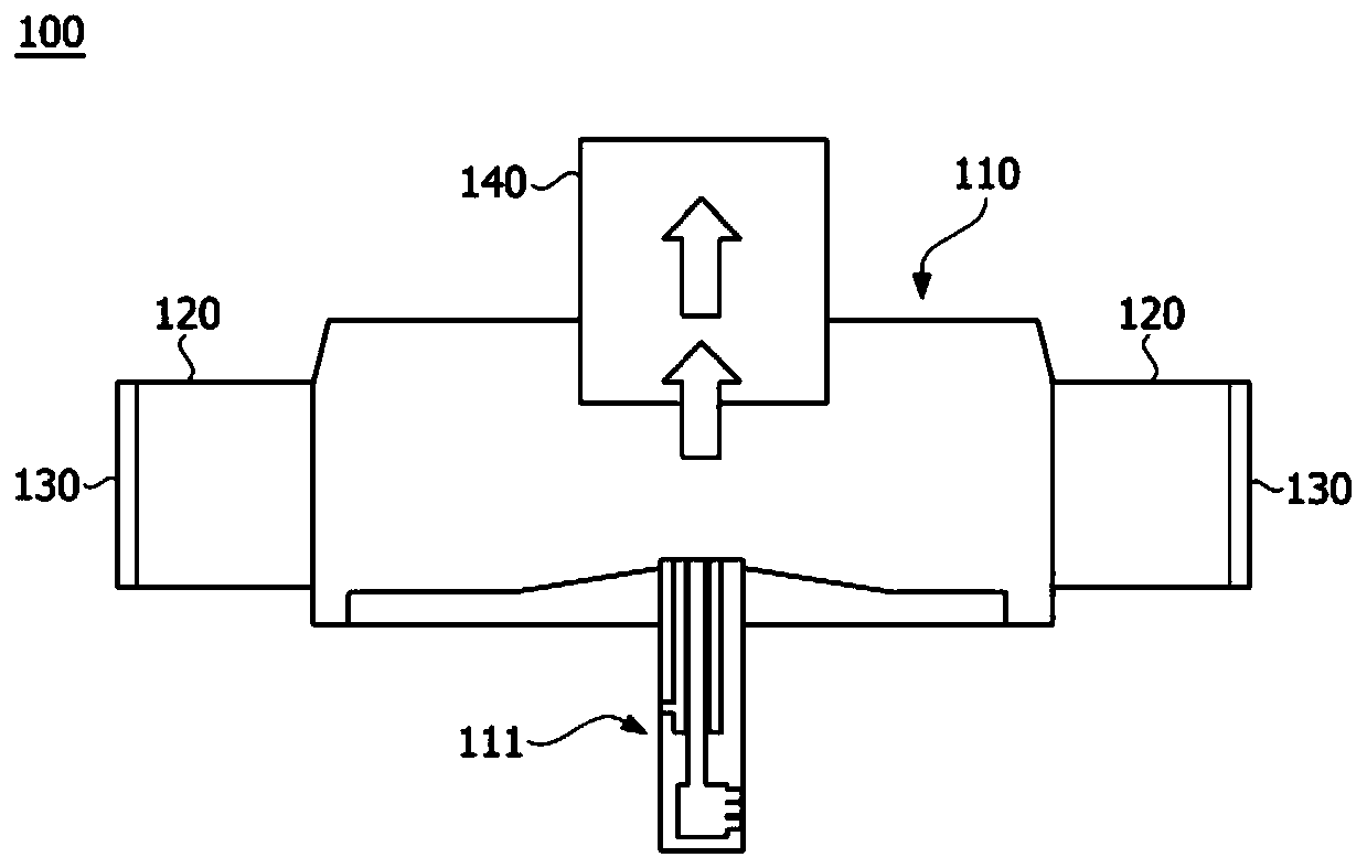
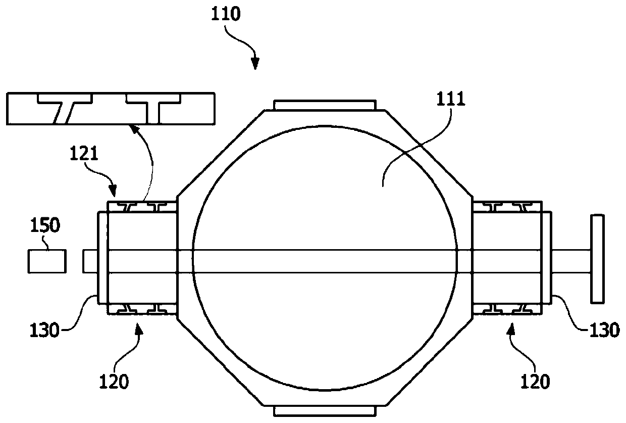
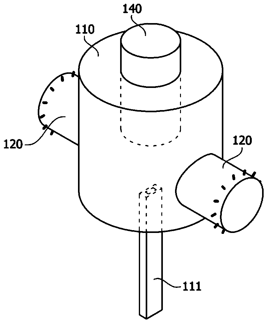
[0026] figure 1 with figure 2 is a schematic diagram showing a common reactor (100) for nanoparticle production, image 3 with Figure 4 is showing figure 1 The main part perspective view of the reactor (100) shown for the production of nanoparticles, Figure 5 is showing image 3 Simulation results of particle trajectories in a reactor.

[0027] The reactor (100) inc...


PUM


Abstract

The present invention relates to a nanoparticle production reactor. An aspect of the present invention provides a nanoparticle production reactor comprising: a main chamber including a first nozzle through which a raw gas is supplied; a lens housing which is connected to the main chamber to allow fluid to move therebetween and includes a second nozzle for supplying flushing gas thereinto; a lens mounted on the lens housing; a light source for emitting a laser such that the laser passes through the lens to reach a raw gas in the main chamber; and a hood for discharging a nanoparticle produced in the main chamber, wherein the lens housing is provided to have at least a partial region having a sectional area decreasing along a direction toward the main chamber.

Description

technical field [0001] The invention relates to a reactor for the production of nanoparticles. [0002] This application claims the benefit of priority based on Korean Patent Application No. 10-2017-0114288 filed on September 7, 2017, the entire disclosure of which is incorporated herein by reference. Background technique [0003] In general, laser pyrolysis is a method of forming nanoparticles by irradiating a raw material with a laser to decompose the raw material. [0004] By using laser pyrolysis of silane gas (SiH 4 ) capable of synthesizing silicon nanoparticles. In such devices, it is important to have a good collection of the synthesized nanoparticles without loss in order to increase the productivity. [0005] The laser pyrolysis reaction equipment is equipped with an optical lens through which the laser beam passes. If the lens is contaminated by nanoparticles, the lens may be damaged. [0006] In order to prevent this, the lens is installed to be separated fro...

Claims


Application Information

Patent Timeline
Patent Type & Authority Applications(China)
IPC IPC(8): B01J6/00B01J19/12B82Y40/00
CPCB82Y40/00B01J19/121B01J6/008B01J4/002B01J19/06B01J19/26B01J2219/0869B01J2219/0875B01J2219/12C01B33/029C01P2004/64
Inventor 金恩贞崔峻源郑镇美林艺勋辛富建
Owner LG CHEM LTD
Why Eureka
Try Eureka