

Jet-type thick oil diluting and mixing tool
A jet-type, heavy oil technology, applied in fluid mixers, mixers, production fluids, etc., can solve problems such as slug flow, increased energy consumption of the pumping system, and waste of thin oil
- Summary
- Abstract
- Description
- Claims
- Application Information
AI Technical Summary
Problems solved by technology
Method used
Image

Examples
Embodiment 1
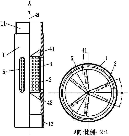
[0039] Such as Figure 1 to Figure 4 As shown, a jet-type thick oil mixed with dilute mixing tool includes an outer cylinder (1), a wing plate (2), an upper plug (41), a lower plug (42), and the outer cylinder (1 ) is provided with a thin oil port (5), and a first connection thread (11) and a second connection thread (12) are provided at both ends; a jet hole (3) is provided on the wing plate (2), two The wing plate (2) forming an included angle α together with the upper plug (41) and the lower plug (42) form a jet cavity. There are three groups of jet chambers, which are evenly distributed and fixed on the inner wall of the outer cylinder (1), arranged parallel to the geometric centerline (a) of the outer cylinder (1); and the jet holes (3) of the jet chamber ) total area is not greater than the thin oil port (5) area. Wherein, the upper plug (41) and the lower plug (41) are tapered structures; the thin oil port (5) is an A-shaped keyway structure.
[0040] Such as figur...
Embodiment 2
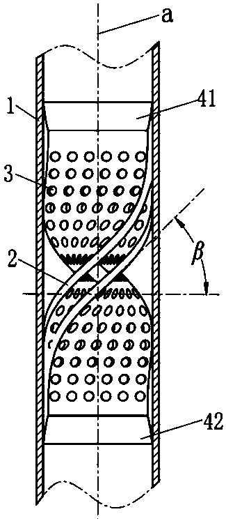
[0043] Such as Figure 5As shown, this embodiment is basically the same as Embodiment 1. The difference is that the jet cavity is composed of two parallel wings (2) (wing angle: α=0°), and the geometric center line of the jet cavity and the outer cylinder (1) (a) Arranged in a helical shape, the value range of the helix angle β of the wing plate: 45°≦β≦75°. The helix angle of the thin oil port (5) is the same as the helix angle β of the wing plate.
[0044] The existence of the wing plate helix angle β enables the heavy oil or mixed oil to form a circumferential rotation and cause a certain degree of turbulent flow during the upward return process, which is beneficial to further improve the mixing uniformity of the oil.
Embodiment 3
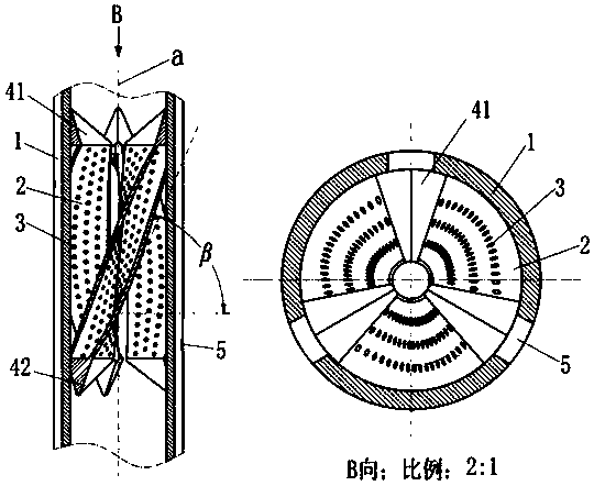
[0046] Such as Figure 6 As shown, this embodiment is basically the same as Embodiment 1. The difference is that: the jet cavity is helically arranged with the geometric center line (a) of the outer cylinder (1), and the value range of the helix angle β of the wing plate is: 45°≦β≦75°; The helix angle of the oil port is the same as the wing plate helix angle β. Moreover, there is no direct contact between the jet cavities, that is, the thick oil or mixed oil channels (jet mixing regions) separated by the jet cavities communicate with each other.
[0047] In this embodiment, the blending areas are connected, which is more suitable under the condition of low viscosity of heavy oil, or under the condition that secondary blending process is required in the lifting process of heavy oil. For oil with better fluidity, the solution adopted in this embodiment can further improve its fluidity, so as to fully utilize fluid kinetic energy and effectively improve the mixing effect.
PUM
 Abstract
Description
Claims
Application Information