
A milling head for milling inner cavity curved grooves

A milling processing and curved groove technology, which is applied in metal processing equipment, milling machine equipment, manufacturing tools, etc., can solve the problems of not meeting the processing requirements, entering the inner cavity of the part, not suitable for processing curved grooves, etc.

Active Publication Date: 2021-07-06
XIAN KUNLUN IND GRP
View PDF10 Cites 0 Cited by
  • Summary
  • Abstract
  • Description
  • Claims
  • Application Information

AI Technical Summary

Problems solved by technology

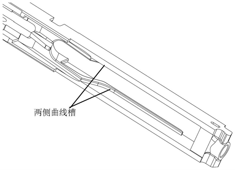
For a transmission frame part of a product, the curved groove in the inner cavity is the key structure of the part, which has an important impact on the function of the part; the curved groove width is 39mm, the groove depth is 35mm, the minimum curvature radius is 30mm, and it is required to clear the angle with the root of the side wall. In terms of technology, it is considered to use disc cutter or T-shaped cutter for processing, but the depth of the groove is greater than the minimum radius of curvature, that is to say, the center of the cutter must enter the inner cavity of the part, so it cannot be processed; after investigation, the structure of the commercial milling head on the market is not suitable. Processing such curved grooves, and the minimum groove width to be processed must reach 80mm, which does not meet the processing requirements

Method used


Image

  • A milling head for milling inner cavity curved grooves
  • A milling head for milling inner cavity curved grooves
  • A milling head for milling inner cavity curved grooves

Examples


Embodiment Construction

[0037] The embodiments described below by referring to the figures are exemplary and are intended to explain the present invention and should not be construed as limiting the present invention.

[0038] In describing the present invention, it should be understood that the terms "center", "longitudinal", "transverse", "length", "width", "thickness", "upper", "lower", "front", " Orientation indicated by rear, left, right, vertical, horizontal, top, bottom, inside, outside, clockwise, counterclockwise, etc. The positional relationship is based on the orientation or positional relationship shown in the drawings, which is only for the convenience of describing the present invention and simplifying the description, rather than indicating or implying that the referred device or element must have a specific orientation, be constructed and operated in a specific orientation, Therefore, it should not be construed as limiting the invention.

[0039] The following examples refer to Fig...


PUM


Abstract

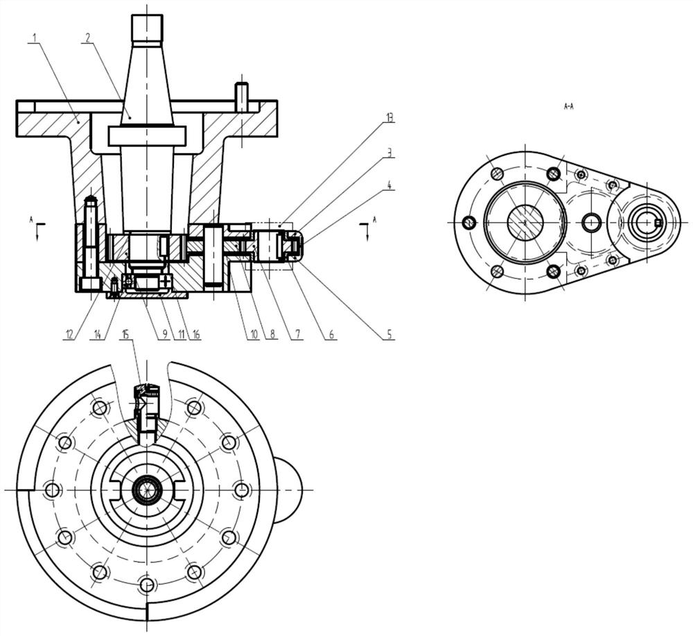
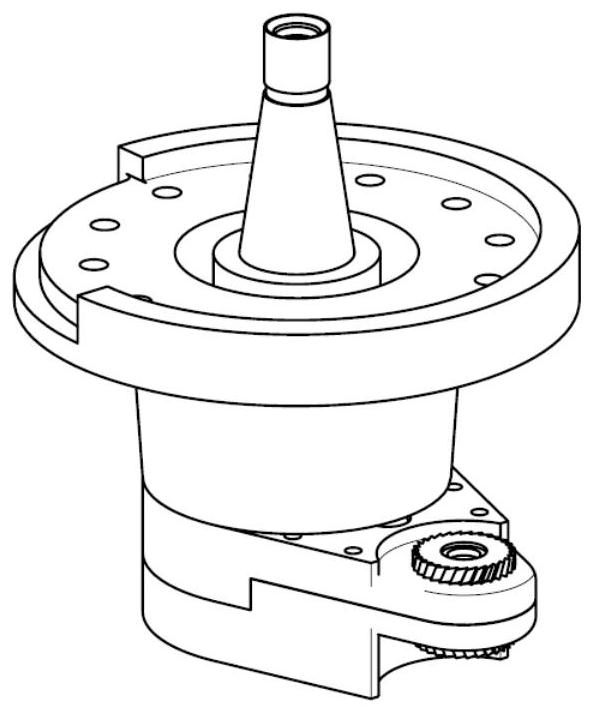
The invention relates to a milling head for milling inner cavity curved grooves, which belongs to the field of machining; it includes a special handle and a special cutter; the special cutter is installed on the milling machine through the special handle; the special handle includes a shell, an upper cover, a lower Cover, shaft, pin shaft, shaft sleeve, first gear, second gear, third gear, bearing and bearing cover; the gear transmission box is composed of the shell, the upper cover and the lower cover, and the shaft, the first gear, the second gear The second gear and the third gear are installed in the gear transmission box to realize the transmission control of the special tool. The special cutter is an I-shaped rotary body, and two cutters are coaxially and fixedly installed at both ends of the optical axis. The parameters of the two cutters are the same, one is left-handed and the other is right-handed. According to the curved groove of the inner cavity, the present invention designs a special tool handle and a special tool. The special tool handle drives the special tool to rotate through the transmission of the gear set for processing, which increases the transmission torque by 20%, improves the cutting efficiency by 40%, and can realize the curve of the special structure. Slot milling.

Description

technical field [0001] The invention belongs to the field of machining, and in particular relates to a milling head for milling inner cavity curved grooves. Background technique [0002] refer to figure 1 . For a transmission frame part of a product, the curved groove in the inner cavity is the key structure of the part, which has an important impact on the function of the part; the curved groove width is 39mm, the groove depth is 35mm, the minimum curvature radius is 30mm, and it is required to clear the angle with the root of the side wall. In terms of technology, it is considered to use disc cutter or T-shaped cutter for processing, but the depth of the groove is greater than the minimum radius of curvature, that is to say, the center of the cutter must enter the inner cavity of the part, so it cannot be processed; after investigation, the structure of the commercial milling head on the market is not suitable. Processing such curved grooves, and the minimum groove width...

Claims


Application Information

Patent Timeline
Patent Type & Authority Patents(China)
IPC IPC(8): B23C9/00B23C3/34
CPCB23C3/34B23C9/005
Inventor 车晓志何家明梁文云康凯田东徐鸿洁王婉
Owner XIAN KUNLUN IND GRP
Learn More