
Laser cladding head combining underwater powder feeding and wire feeding and its processing method

A technology of laser cladding and wire feeding, which is applied in the coating process and coating of metal materials, etc., can solve the problem that it is difficult to maintain the local drying space of the workpiece to be welded, it is difficult to guarantee, and it is difficult to realize the technical effect of saving high-pressure welding shielding gas, etc. problems, to ensure the quality of cladding processing, save the amount of use, and maintain good airflow stability.

Active Publication Date: 2021-11-23
SOUTHEAST UNIV
View PDF17 Cites 0 Cited by
  • Summary
  • Abstract
  • Description
  • Claims
  • Application Information

AI Technical Summary

Problems solved by technology

[0008] Chinese application 201910198415.7 discloses a laser cladding processing head combining laser wire feeding and powder feeding, which specifically discloses that two conditions are required for the realization of wire feeding in the laser ring: (1) the need to form a hollow ring-shaped spot of precise size, However, the complex optical system has poor stability and is highly dependent on the processing environment, which is difficult to guarantee; (2) The metal wire does not deform during the wire feeding process, and generally the slender metal wire will move and the contact between the metal wire and the workpiece will It produces a large resistance and is prone to deformation. Once the deformation occurs, the contact position between the laser spot and the metal wire will change, and the cladding process will fail
[0009] Chinese application 201711252672.1 discloses a double-layer drainage device for underwater laser cladding and underwater laser-arc hybrid welding. According to the content recorded in the application, the high-pressure welding shielding gas enters the inner drainage cavity through the air inlet of the inner drainage cavity , and then flow out from the lower end of the inner drainage cavity, although the inner diameter of the inner drainage cavity is not recorded in the application document, but according to the disclosed content of the attached drawing, the inner diameter of the inner drainage cavity is much larger than the aperture of the air inlet of the inner drainage cavity, At the same time, through the technical contents recorded in this application, the following facts can be obtained: 1. Before processing, the air pressure of the welding shielding gas discharged from the inner drainage cylinder is greater than the air pressure of the airflow discharged from the outer drainage cylinder, so as to ensure the drainage of the inner layer The welding shielding gas discharged from the cylinder squeezes the airflow discharged from the outer drainage cylinder to be discharged from the contact surface between the rubber skirt bushing and the workpiece to be welded, and then forms a local dry space on the workpiece to be welded underwater; 2. During processing At this time, the air pressure of the high-pressure welding shielding gas discharged from the inner drainage cylinder still needs to be greater than the air pressure of the airflow discharged from the outer drainage cylinder, otherwise it is difficult to maintain the local dry space on the workpiece to be welded
Therefore, the applicant believes that the technical solution adopted in this document is difficult to achieve the technical effect of "saving high-pressure welding shielding gas"

Method used


Image

  • Laser cladding head combining underwater powder feeding and wire feeding and its processing method
  • Laser cladding head combining underwater powder feeding and wire feeding and its processing method
  • Laser cladding head combining underwater powder feeding and wire feeding and its processing method

Examples


Embodiment Construction

[0046] The following will clearly and completely describe the technical solutions in the embodiments of the present invention with reference to the accompanying drawings in the embodiments of the present invention. Obviously, the described embodiments are only some, not all, embodiments of the present invention. The following description of at least one exemplary embodiment is merely illustrative in nature and in no way taken as limiting the invention, its application or uses. Based on the embodiments of the present invention, all other embodiments obtained by persons of ordinary skill in the art without creative efforts fall within the protection scope of the present invention. The relative arrangements, expressions and numerical values ​​of components and steps set forth in these embodiments do not limit the scope of the present invention unless specifically stated otherwise. At the same time, it should be understood that, for the convenience of description, the sizes of the...


PUM

PropertyMeasurementUnit
diameteraaaaaaaaaa

Abstract

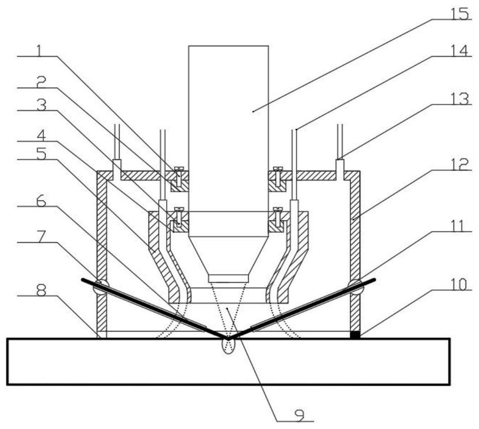
The invention discloses a laser cladding head combined with underwater powder feeding and wire feeding and a processing method thereof. The laser cladding head includes a drainage outer cover, a drainage inner cover, and a cladding processing head; the cladding processing head includes a columnar cavity and a conical cladding head; the conical cladding head is suspended in the drainage inner cover, and the outer walls of the columnar cavity are respectively connected to The closed end of the drainage outer cover and the closed end of the drainage inner cover are connected and fixed; the drainage outer cover includes the outer cover body and the first air intake pipeline; the drainage inner cover includes the inner cover body and the second air intake pipeline; the second air intake pipeline includes a connected inlet Air section, air outlet section; the air inlet section is straight and the air inlet end of the air inlet section runs through the closed end of the inner cover body; the air outlet section is arc-shaped and the air outlet end of the air outlet section runs through the open end surface of the inner cover body. The included angle between the axis of the gas outlet section and the axis of the laser output channel is an acute angle. Therefore, the cladding processing head of the present invention maintains good airflow stability during processing, effectively ensures the quality of cladding processing, and saves the amount of shielding gas used.

Description

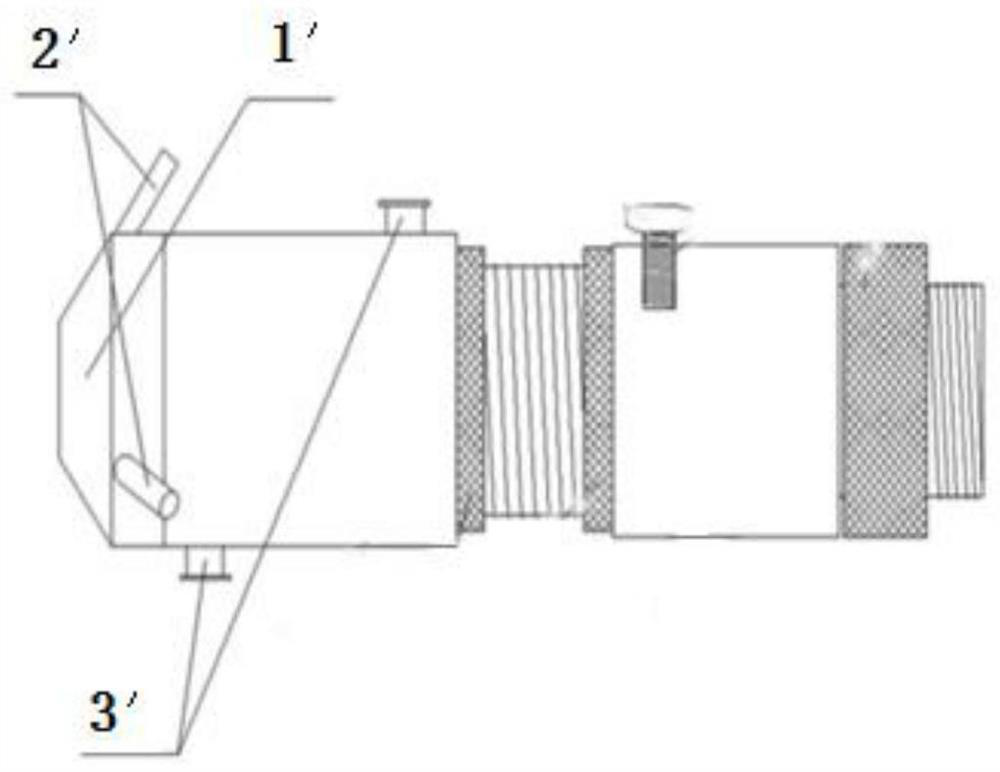
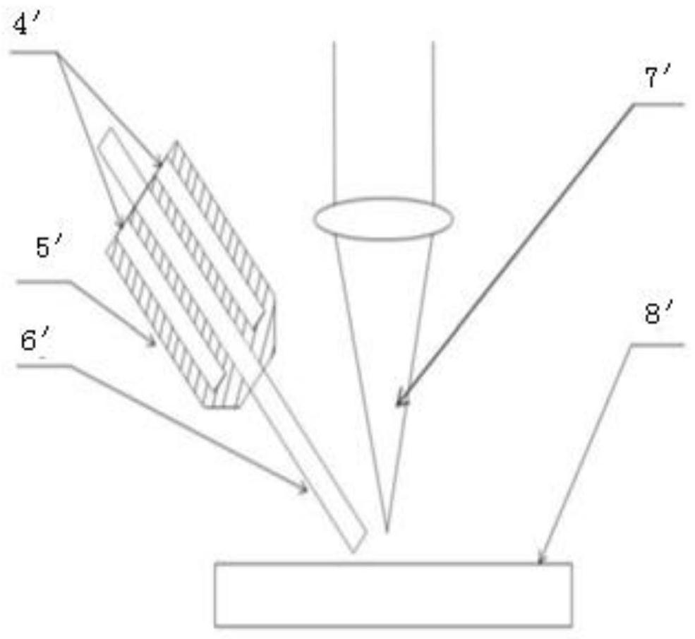
technical field [0001] The invention belongs to the technical field of underwater laser processing, and in particular relates to a laser cladding head combined with underwater powder feeding and wire feeding and a method thereof. Background technique [0002] The laser cladding process is a kind of laser processing process. The end effector that realizes this process is called a laser cladding head. The laser cladding head can send laser, metal wire or metal powder to the plane to be processed at the same time, and can realize laser cladding. A mechanical device that interacts with wire or powder. [0003] Laser powder-feeding cladding head and laser wire-feeding cladding head product technology has been very mature, commercialization has basically been realized, and there are a large number of patents for expression. The publication number is CN204135337U patent discloses a kind of laser powder feeding type cladding head, its structure is as follows figure 1 As shown, in ...

Claims


Application Information

Patent Timeline
Patent Type & Authority Patents(China)
IPC IPC(8): C23C24/10
CPCC23C24/103
Inventor 倪中华孙桂芳严乾卢轶王占栋
Owner SOUTHEAST UNIV
Learn More