
Membrane type microcapillary precooler cooling refrigerant gas collecting device

A technology for cooling working fluid and gas collecting devices, which is applied in the direction of machines/engines, internal combustion piston engines, mechanical equipment, etc., and can solve the problems of large flow resistance, many sealing parts, large volume and weight of the precooler, and improve the structure Reliability, improve the overall rigidity, and reduce the effect of process difficulty

Active Publication Date: 2020-04-24
BEIJING POWER MACHINERY INST
View PDF7 Cites 2 Cited by
  • Summary
  • Abstract
  • Description
  • Claims
  • Application Information

AI Technical Summary

Problems solved by technology

Although the existing precooler structure can achieve high-efficiency heat exchange and has the characteristics of high compactness and high power density, but because the cooled air enters the precooler in the radial direction perpendicular to the axis and flows out in the axial direction, the flow of the precooler At the same time, due to the need for a relatively complicated molding process for the microtubes and welding and assembly of the diaphragm unit, the manufacture of the pre-cooler is difficult and costly; in addition, the pre-cooler passes through multiple heat exchange diaphragms The air collecting pipe on the unit is connected to the external cooling medium pipeline, which makes the peripheral connection pipeline of the precooler complex, with many sealing parts, large volume and weight, and is not conducive to the structural reliability of the precooler

Method used


Image

  • Membrane type microcapillary precooler cooling refrigerant gas collecting device
  • Membrane type microcapillary precooler cooling refrigerant gas collecting device
  • Membrane type microcapillary precooler cooling refrigerant gas collecting device

Examples


Embodiment Construction

[0025] The present invention will be described in detail below with reference to the accompanying drawings and examples.

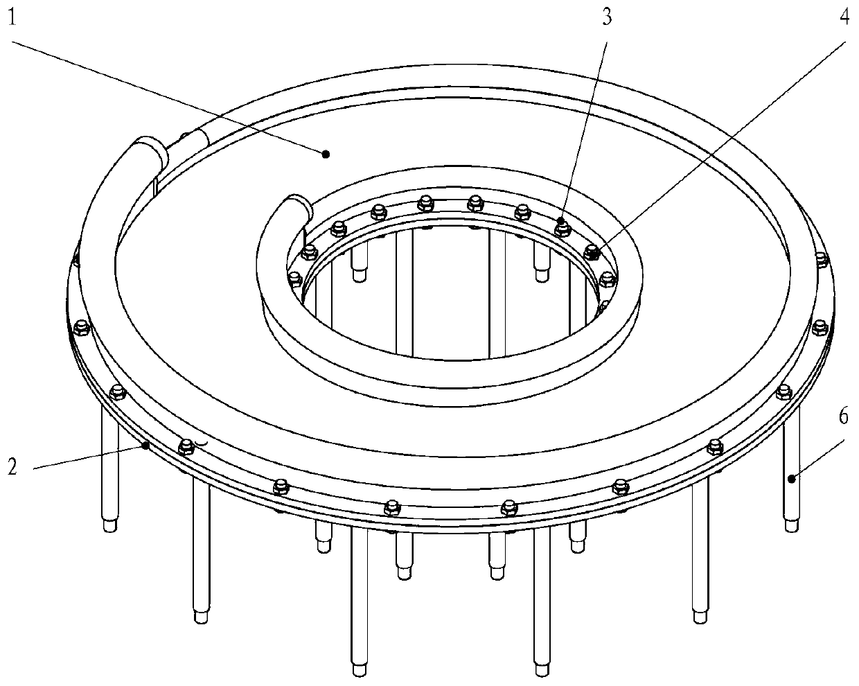
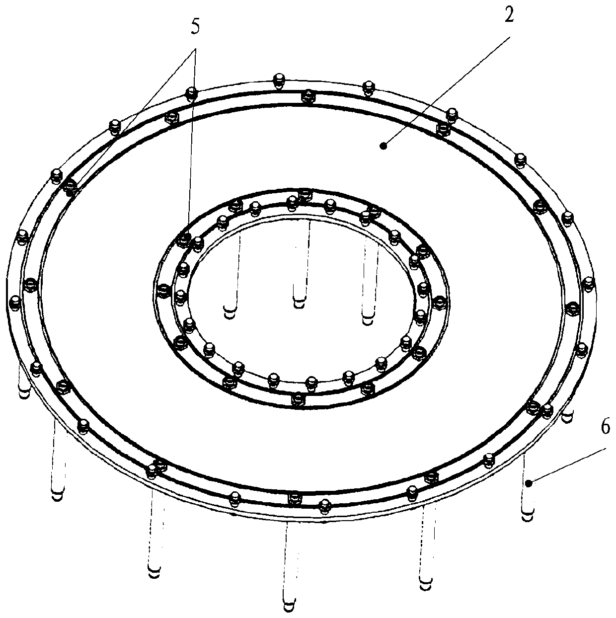
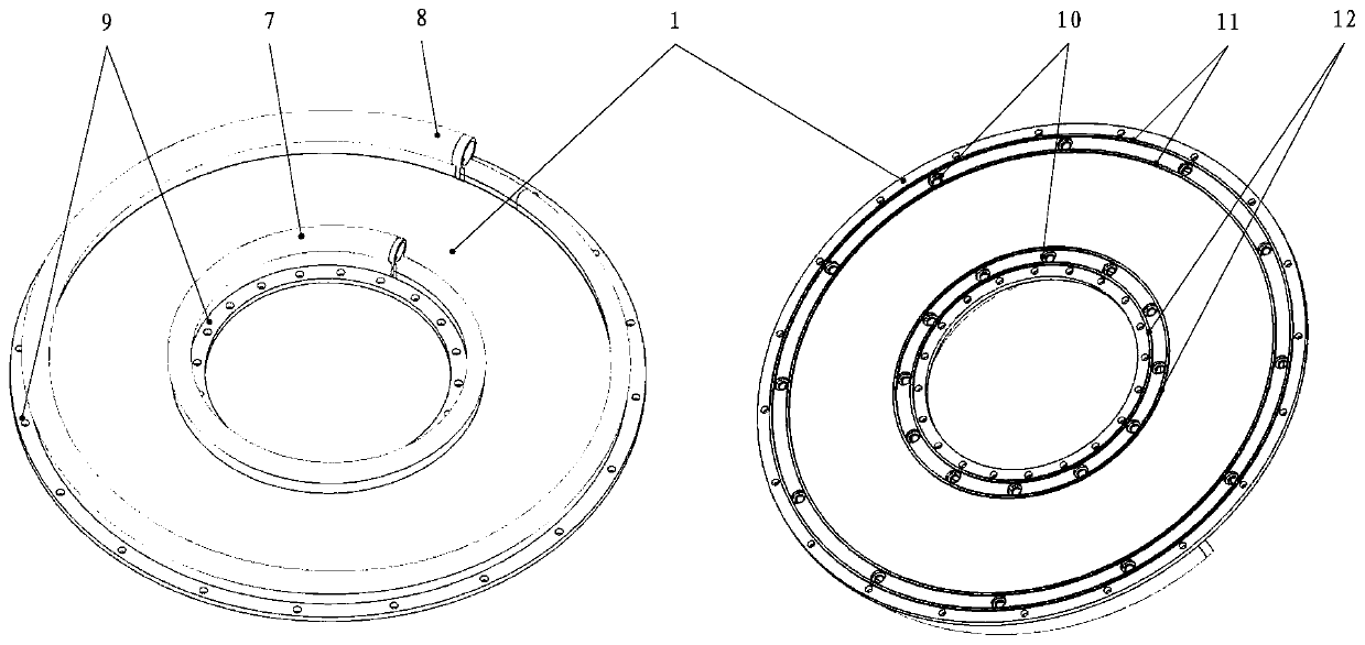
[0026] The present invention provides a diaphragm-type microtube precooler cooling working fluid gas collection device, which includes an integrated end cover 1, a support plate 2, a suture screw 3, a suture nut 4 and a lock nut 5;

[0027] One side of the integrated end cover 1 is provided with an annular gas collection pipeline 7 for the cooling medium to flow into the precooler and an annular gas collection pipeline 8 for the outflow of the precooler. The cross-sectional area of ​​the annular gas collection pipeline 7 of the precooler gradually decreases along the flow direction, and the cross-sectional area of ​​the annular gas collection pipeline 8 on the integrated end cover 1 for cooling working fluid to flow out of the precooler gradually decreases along the flow direction. Increased, the annular air collecting pipe 7 from which the cooling working...


PUM


Abstract

The invention relates to a membrane type microcapillary precooler cooling refrigerant gas collecting device. The structure is formed by assembling an integrated end cover, a supporting plate, sewing screws, sewing nuts and locking nuts. According to the structural size and number of the spiral microcapillary heat exchange membranes and inlet and outlet parameters of a cooling refrigerant, the structural size parameters of the membrane type microcapillary precooler cooling refrigerant gas collecting device and component parts thereof are determined, on the basis of completing the manufacturingof parts, firstly, assembly of the supporting plate and precooler heat exchange membrane gas collecting pipes is carried out, then the integrated end cover, the supporting plate and the precooler heatexchange membrane gas collecting pipes are assembled, and finally, sewing of the integrated end cover and the supporting plate is completed through the sewing screws and sewing nuts, thus realizing the precooler cooling refrigerant gas collecting device. The structure effectively reduces the connecting pipelines and interfaces of the precooler and peripheral components, is conducive to improvingthe structural reliability of the precooler, also facilitates assembly of the precooler cooling refrigerant gas collecting device, and has good manufacturability.

Description

technical field [0001] The invention belongs to the technical field of precooling power, and in particular relates to a cooling working medium gas collecting device of a diaphragm microtube precooler. Background technique [0002] Pre-cooling the engine is to pre-cool the incoming gas at the inlet of the air compressor with the help of the pre-cooler and its related components and systems, reduce the gas temperature at the inlet of the air compressor, increase the mass flow rate of the gas at the inlet of the compressor, and broaden the compressor. Efficient working range, so that the engine can adapt to the power demand of the aircraft under high-speed conditions, is one of the important development directions of aerospace vehicle power. [0003] As the core component of the precooling engine, the precooler plays a very important role in widening the operating speed range of the engine and improving the thrust-to-weight ratio of the engine. In order to meet the requirement...

Claims


Application Information

Patent Timeline
IPC IPC(8): F02B29/04
CPCF02B29/0437F02B29/0462Y02T10/12
Inventor 马同玲王正侯泽兵张志刚何学刚
Owner BEIJING POWER MACHINERY INST
Features
  • Generate Ideas
  • Intellectual Property
  • Life Sciences
  • Materials
  • Tech Scout
  • Unparalleled Data Quality
  • Higher Quality Content
  • 60% Fewer Hallucinations
Learn More