

Vibration isolation device
An isolation device, vibration isolation technology, applied in vibration suppression adjustment, non-rotation vibration suppression, photolithography process exposure device, etc., can solve the problems of large vibration transmission attenuation, heat loss and so on
- Summary
- Abstract
- Description
- Claims
- Application Information
AI Technical Summary
Problems solved by technology
Method used
Image

Examples
Embodiment Construction
[0028] In order to make the object, technical solution and advantages of the present invention clearer, the present invention will be described in further detail below in conjunction with specific embodiments and with reference to the accompanying drawings.
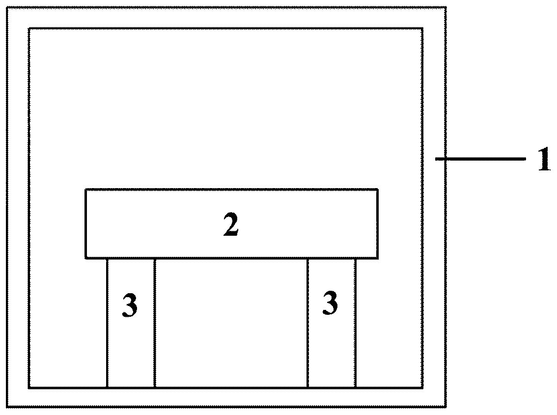
[0029] refer to figure 1 , figure 1 A schematic diagram of the main structure of the extreme ultraviolet lithography vibration isolation device in the embodiment of the present invention is shown. figure 1 The structure includes: a vacuum chamber 1, a main substrate 2 and two vibration isolation systems 3; the main substrate 2 and the vibration isolation system 3 are arranged on the inner wall of the vacuum chamber 1, and the vibration isolation system 3 is arranged on the vacuum chamber 1 and the vibration isolation system 3. Between the main substrate 2.
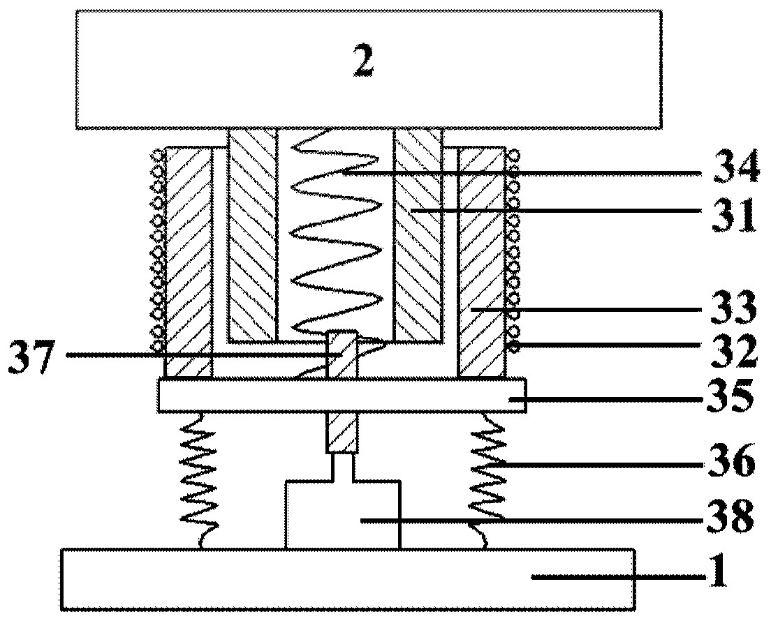
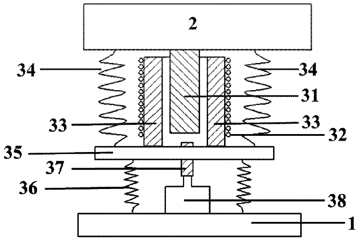
[0030] refer to figure 2 , figure 2 It schematically shows the first structural diagram of the vibration isolation device in the embodiment of the present inven...
PUM
 Abstract
Description
Claims
Application Information