
Micro optical tweezer device and method based on self-focusing lens array

A self-focusing lens and focusing lens technology, applied in the field of optical manipulation, can solve the problems of inability to guarantee the capture force of optical tweezers, softness and easy deformation, poor repeatability of fiber optical tweezers, etc., to facilitate cell sorting and manipulation, ensure capture force, The effect of getting rid of space constraints

Inactive Publication Date: 2020-04-24
JIANGSU RUIJING INST OF OPTO ELECTRONICS CO LTD
View PDF5 Cites 0 Cited by
  • Summary
  • Abstract
  • Description
  • Claims
  • Application Information

AI Technical Summary

Problems solved by technology

[0003] The beam focusing elements in traditional optical tweezers are limited by space and cannot be integrated in high-end microscopic imaging equipment for cell sorting and manipulation; traditional optical tweezers usually only produce one focused beam and can only manipulate a single sample at a time; and traditional optical fibers Optical tweezers have poor repeatability, are soft and easy to deform, and cannot guarantee the capture force of optical tweezers

Method used


Image

  • Micro optical tweezer device and method based on self-focusing lens array
  • Micro optical tweezer device and method based on self-focusing lens array
  • Micro optical tweezer device and method based on self-focusing lens array

Examples


Embodiment 1

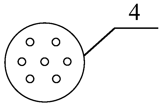
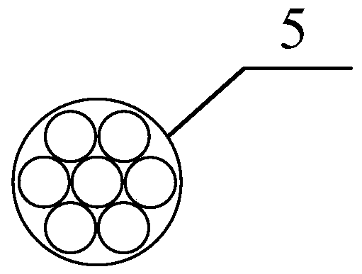
[0030] The structural diagram of the present invention is as figure 1 , a micro-optical tweezers device based on a self-focusing lens array, using 3D printing technology to build the core component of a personalized micro-optical tweezers device, using a high-numerical-aperture self-focusing lens array can produce a high-numerical-aperture tightly focused beam for integration in Cell sorting and manipulation in high-end microscopy imaging equipment. According to the direction of light propagation, they are: laser 1, optical fiber 2, collimator 3, microlens array 4, and self-focusing lens array 5, forming a focused beam and extending into the petri dish 7 to grab the sample 6; the sample 6 is placed on the petri dish 7 In the liquid environment, the liquid environment includes a culture medium.

[0031] In order to further optimize the above technical solution, the output fiber end of the laser is connected to a fiber coupler, and then connected to a collimator. The fiber coup...

Embodiment 2

[0039] A micro-optical tweezers implementation method based on a self-focusing lens array, comprising: a laser beam emitted by a laser 1 passes through an optical fiber 2 and a collimator 3 to form a parallel laser beam, and after the parallel laser beam enters a microlens array 4, N beams are focused Light, where N is greater than or equal to 3, the focused light is then coupled into the self-focusing lens array 5 to form a tightly focused beam of high numerical aperture, and the focused beam extends into the culture medium of the petri dish 7 to grab the sample 6 .

[0040] In order to further optimize the above technical solution, N beams of focused light are respectively incident on N high numerical aperture self-focusing lenses of the self-focusing lens array 5 .

[0041] In order to further optimize the above technical solution, the focused light is incident on the front working surface of the self-focusing lens array 5 at the focal plane of the microlens array 4 .


PUM


Abstract

The invention discloses a miniature optical tweezer device and method based on a self-focusing lens array. The device sequentially comprises a laser, an optical fiber, a collimator, a micro-lens arrayand a self-focusing lens array in a light propagation direction, and a tightly-focused light beam is formed to extend into a culture dish to grab a sample. A plurality of optical tweezers grabbing well positions are generated on a working surface of the a-focusing lens, a plurality of samples can be sorted and operated at the same time, and the application range of the optical tweezers is expanded.

Description

technical field [0001] The invention belongs to the technical field of optical manipulation, and relates to a micro optical tweezers device and method based on a self-focusing lens array. Background technique [0002] Focused laser beams can "clamp" and manipulate microscopic particles (atoms, molecules, etc.) and tiny objects (cells, viruses, etc.) like tweezers. important applications in the field of life sciences. Miniature optical tweezers can get rid of the space limitation of beam focusing elements in traditional optical tweezers, and can be easily integrated into high-end microscopic imaging equipment for cell sorting and manipulation. [0003] The beam focusing elements in traditional optical tweezers are limited by space and cannot be integrated in high-end microscopic imaging equipment for cell sorting and manipulation; traditional optical tweezers usually only produce one focused beam and can only manipulate a single sample at a time; and traditional optical fibe...

Claims


Application Information

Patent Timeline
IPC IPC(8): G02B21/32G02B21/24
CPCG02B21/241G02B21/32
Inventor 刘辰光刘俭赵一轩陈刚
Owner JIANGSU RUIJING INST OF OPTO ELECTRONICS CO LTD
Learn More